Opel Frontera UBS. Manual - part 49


  Index      Opel     Opel Frontera UBS - service repair manual 1998-2002 year


Search            


Content   ..  47  48  49  50   ..


Opel Frontera UBS. Manual - part 49


AIR CONDITIONING  1B–93

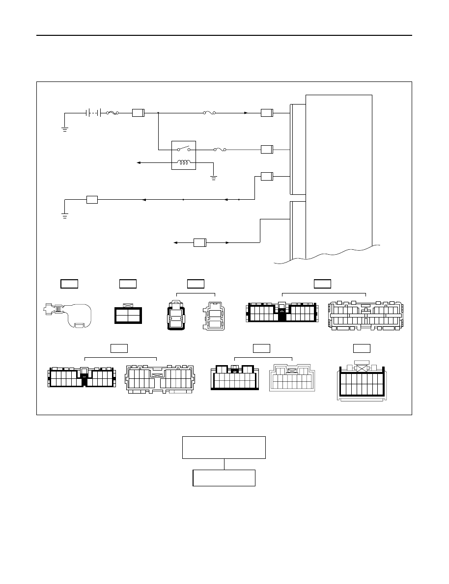
Check of Auto Amplifier (Automatic air conditioner control unit) Power Supply System

• This check is required because a trouble on the auto amplifier (control unit) power supply circuit or

grounding circuit prevents accurate troubleshooting.

Check of auto amplifier

power supply circuit and

grounding circuit.

Chart A

B-18

FL-1 Main
80A

0.5G/R

16

10

7

8

I-32

I-32

C-16

10A

0.3R/W

0.5BR

Backup

Power supply (12V)

Unit ground

Automatic heater/air conditioner control unit

B-18

B-36

H-14

C-20

10A A/C

Relay:
Heater and air
conditioner

0.5B

1.25B

2B

Lighting switch

Lighting switch

H-14

1

H-26

9

H-26

14

H-27

20

H-16

14

2

1

4

3

B-36

1

2

3

4

H-16

H-26

H-27

I-32

1

2

1

2

10 9 8 7 6

5 4 3 2 1

2221201918

1514131211

17

16

1 2 3 4 5

1112131415

6 7 8 9 10

1819202122

16

17

10 11 12 13 14 15

1 2 3 4 5

17 18 19 20

6 7 8 9

16

9 8 7 6

20 19 18 17 16

5

14

15

4

13

3

12

2

11

1

10

20

12

19

11

18

10

17

9

16

8

15

7

14

6

13

5

1 2

3 4

4 3

2 1

12 11 10 9 8 7 6 5

13

14

15

16

17

18

19

20

1 2 3 4 5 6 7 8

9 10 11 12 13 14 15 16

D08RY00175

1B–94 AIR CONDITIONING

Chart "A" : Check of Auto Amplifier Power Supply System

NO

Harness disconnection or improper grounding.

NO

Harness disconnection or improper grounding.

NO

Harness disconnection or trouble on lighting

switch.

NO

Harness disconnection or improper grounding.

Turn off ignition switch.

Power supply system is free of

trouble.

YES

YES

YES

YES

Is battery voltage present between chassis
harness connector terminal No.7 
and ground?

I-32

Is battery voltage present between
chassis harness connector No.8 
and ground?

I-32

Are chassis harness connector No.16 
and body ground 

conducted?

B-18

I-32

Turn on ignition switch (engine is started).
Turn on lighting switch.

Is battery voltage present between chassis
harness connector No.10 

and

ground?

I-32

AIR CONDITIONING  1B–95

Performance and Movement checklist for Automatic Air Conditioner Related Parts

Start the engine, and when the engine coolant reached 60°C check performance and movement of the
related parts according the following checklist.

1. Performance Check Using the Manual Switch

Checking Approach

No.

Item

Acceptance criteria

Condition

Operation

Blowing
temperature
(check movement
of air mix door)

Airflow volume
(check movement
of the mode door)

Set temperature to
25.0°C.

(1) Turn the fan knob

off.

(2) Turn the fan knob

from LOW to HI.

(1) The fan shall be stopped, thus

stopping air blow, too.

(2) Airflow volume shall change

from LOW to HI.

Blowing
temperature
(check movement
of the mode door)

Set temperature to
25.0°C.
Set the fan knob to HI.

Press the mode switch
to change the blow port
mode sequentially from
the VENT through BI-
LEVEL, FOOT up to
DEF.

LED corresponding to each mode
shall be turned on and the blow
port mode shall be switched
smoothly.

The
interior/outside air
switching mode
(check movement
of intake door)

Set temperature to
25.0°C.

Turn the LED off using
the interior/outside air
switch (this introduces
the outside air intake
mode). Then, the set
fan knob to HI and
press the
interior/outside switch
to turn on the LED.

The LED indication shall be
switched from OFF to ON
accompanying a change in air
blowing sound.

Compressor

Set the temperature to
FC. (Outside air
temperature is 0C or
above and interior
temperature at ordinary
temperature.)

Press the "OFF" switch.
(1) Press the Auto

switch.

(2) Press the Air

Conditioner switch.

(1) As the fan knob is set to the

Auto position, the A/C switch
LED shall come on and the
compressor shall be turned on.

(2) As the A/C LED comes off, the

compressor shall be turned off.

Auto switch must be
turned on
(FAN-AUTO
MODE-AUTO)

(1) Select FC for the

setup temperature.

(2) Select FH for the

setup temperature.

Then, select the
MAX Control.

(1) Cold air shall be blown out.
(2) Hot air shall be blown out.

1

2

3

4

5

1B–96 AIR CONDITIONING

Checking Approach

No.

Item

Acceptance criteria

Condition

Operation

Change the
temperature gradually
starting with 20°C up to
30°C.

The following phenomena shall be
recognized.
• Temperature of blown air: Cold

air is changed to hot air.

• Change in the air flow volume.
• The blow port mode LED

indication changes in the
following sequence:

Select FH for the
temperature.

Cold air shall be blown out.
The following LEDs shall come on.

• Blow port mode :

• Fan speed: Max Hi

Select FC for the
temperature.

The LED shall come on.
Cold air shall be blown out.

The following LEDs shall come on:

• Blow port mode :

• Intake mode

• Fan speed : MAX Hi

• A/C

1

Full Auto function

FAN KNOB “AUTO”
MODE SW “AUTO”

2. Check of Full Auto Function

(VENT)

(FOOT)

(BI-LEVEL)

F01RX003

F01RX002

F01RX004


Content   ..  47  48  49  50   ..