Opel Frontera UBS. Manual - part 12


  Index      Opel     Opel Frontera UBS - service repair manual 1998-2002 year


Search            


Content   ..  10  11  12  13   ..


Opel Frontera UBS. Manual - part 12


00 – 20 SERVICE INFORMATION
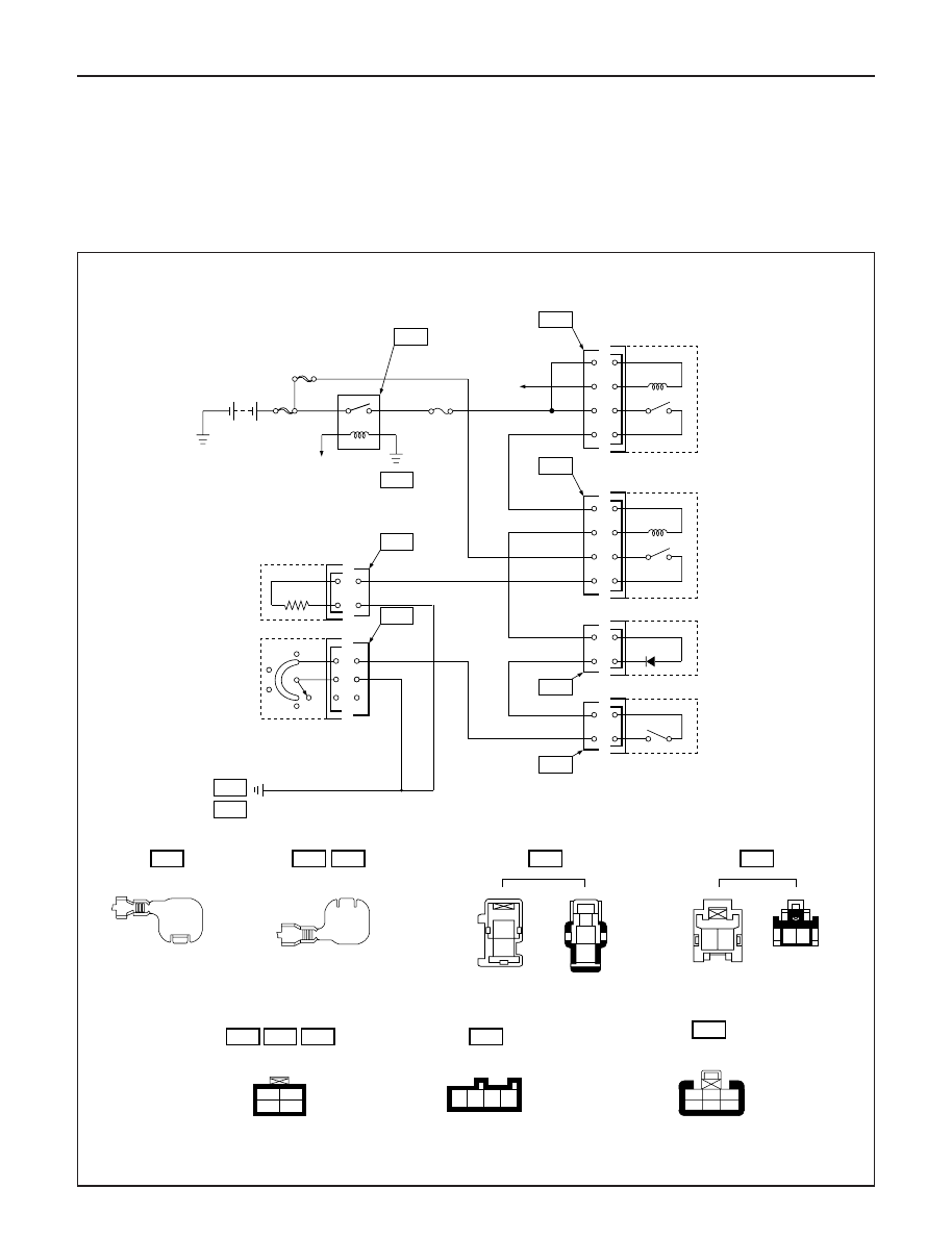
CERAMIC HEATER

When the fan control knob (fan switch) turns on
with the temperature control knob set to “FULL
HOT” (full hot switch “ON”), the ceramic heater in
the heater unit turns on and the blow temperature
goes up. When the ceramic heater turns on, FICD

starts to operate at the same time. When either one
of the fan switch, the full hot switch or the thermo
switch (which turns on when the coolant tempera-
ture gets below 80

°

C (176

°

F) turns off, the ceramic

heater also turns off.

FL-3

40A

C/HEATER

RELAY; 
HEATER A/C

ECM
(J1-23)

2

4

1

3

C-20
10A
A/C

FL-1

80A

MAIN

B-18

B-1

B-36

1

3

X-12

2

4

1

3

X-21

2

4

1

2

1

2

4

1

3

2

4

1

1

2

CERAMIC
HEATER

FAN SW.

B-19

B-48

I-18

B-44

B-49

RELAY;
THERMO
SW

RELAY;
CERAMIC
HEATER

DIODE

FULL HOT
SW.

B-1

B-48

1

2

1

2

2 1

1 2

B-49

I-18

2

1

3

5

4

6

1

2

3

4

B-36

X-12

X-21

1

2

3

4

B-44

(RHD)

B-2

(LHD)

B-2

D08RWD66

SERVICE INFORMATION  00 – 21

CERAMIC HEATER DOES NOT OPERATE

ARE NO. FL-3 (40A) AND NO. C-20 (10A) OK? 

YES

NO

REPLACE

REPLACE

REPLACE

REPLACE

ARE A/C AND CERAMIC HEATER RELAYS OK?

YES

NO

ARE BLOWER MOTOR AND FAN SW. OK?

YES

NO

IS FULL HOT SW. OK?

DOES TEMP. CONTROL LINK (HEATER UNIT)
OPERATE CORRECTLY?

YES

NO

REPLACE

TURN THE IGNITION SW. “ON” (ENGINE IS RUNNING)

CERAMIC HEATER “ON”

CHECK TO SEE IF BATTERY VOLTAGE IS PRESENT AT
CHASSIS SIDE CONNECTOR TERMINAL NO. B48-1

YES

NO

OPEN CIRCUIT

CHECK TO SEE IF BATTERY VOLTAGE IS PRESENT AT
CHASSIS SIDE CONNECTOR TERMINAL NO. B48-2

YES

NO

CERAMIC HEATER DEFECTIVE

CHECK THE CERAMIC HEATER OR CERAMIC HEATER-
RELATED HARNESS FOR A POOR GROUND AND REPAIR
IT AS NECESSARY

YES

NO

DOES CONTROL LEVER CABLE OPERATE CORRECTLY?

IS THERMO RELAY OK?

YES

NO

NO

YES

ADJUST OR REPLACE

REPAIR OR REPLACE
TEMP. CONTROL UNIT

00 – 22 SERVICE INFORMATION

CERAMIC HEATER DOES NOT STOP

WHEN THE IGNITION SW. “OFF”, DOES CERAMIC HEATER
STOP?

YES

NO

CERAMIC HEATER RELAY DEFECTIVE

SHORT CIRCUIT BETWEEN CHASSIS SIDE RELAY TERMINAL
NO. X12-3 AND CHASSIS SIDE CONNECTOR TERMINAL
NO. B49-1

SERVICE INFORMATION  00 – 23

AIR CONDITIONING CYCLE TROUBLESHOOTING

No cooling or insuffi-
cient cooling

Insufficient velocity
of cooling air

1. Magnetic clutch does not run

2. Compressor is not rotating properly

Drive belt loosened or broken

Magnetic clutch face is not
clean and slips

Incorrect clearance between
magnetic drive plate and pulley

Compressor oil leaks from shaft
seal or shell

Compressor seized

3. Insufficient or excessive charge of

refrigerant

4. Leaks in the refrigerant system

5. Condenser clogged or insufficient

radiation

6. Temperature control link unit of the

heater unit defective

7. Unsteady operation due to foreign

substance in expansion valve

8. Poor operation of electronic thermo-

stat

1. Evaporator clogged or frosted

2. Air leaking from cooling unit or air

duct

3. Blower motor does not rotate prop-

erly

Refer to “MAGNETIC CLUTCH”
troubleshooting

Adjust the drive belt to the specified
tension or replace the drive belt

Clean the magnetic clutch face or
replace

Adjust the clearance (Refer to
Section 1D “COMPRESSOR OVER-
HAUL”

Replace the compressor

Replace the compressor

Discharge and recover refrigerant.
Recharge to specified amount.

Check refrigerant system for leaks
and repair as necessary
Discharge and recover refrigerant.
Recharge to specified amount.

Clean the condenser or replace as
necessary

Check radiator or condenser fan
function

Repair the link unit

Replace the expansion valve

Check electronic thermostat and
replace as necessary

Check evaporator core and replace
or clean the core

Check evaporator and duct connec-
tion, then repair as necessary

Refer to Section 00 for “FAN
CONTROL KNOB (FAN SWITCH)”
troubleshooting

* For the execution of the charging and discharging operation in the table above, refer to the “RECOVERY,

RECYCLING, EVACUATING AND CHARGING” in section 1B.

TROUBLE

POSSIBLE CAUSE

CORRECTION


Content   ..  10  11  12  13   ..