Opel Frontera UE. Manual - part 896
6D2–2
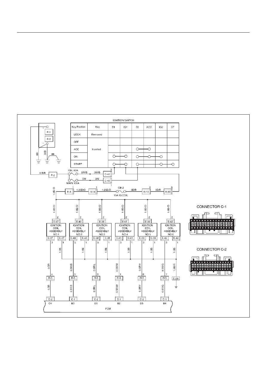
IGNITION SYSTEM (6VD1 3.2L)
General Description
Ignition is done by the electronic ignition (El) that directly
fires the spark plugs from ignition coils through spark plug
wires without using a distributor. A pair of ignition coils for
the cylinders having different phases by 360
°
(No.1 and
No.4,No.2 and No.5,No.3 and No.6) are fired
simultaneously.
Since the cylinder on exhaust stroke requires less energy
to fire its ignition plug, energy from the ignition coils can be
utilized to fire the mating cylinder on compression stroke.
After additional 360
°
rotation, respective cylinder strokes
are reversed.
The EI consists of six ignition coils,ignition control
module, crank angle sensor, powertrain control module
(PCM) and other components.
The ignition coils are connected with the PCM by means
of a 32 pin connector.
The ignition control module turns on/off the primary circuit
of ignition coils, and also it controls the ignition timing at
the engine speed below 538 rpm.
A notch in the timing disc on the crankshaft activates the
crank angle sensor which then sends information such as
firing order and starting timing of each ignition coil to the
PCM.
Further, the El employs ignition control (IC) to control
similar to a distributor system.
By receiving signals such as crank position,engine
speed, water temperature and Manifold Absolute
Pressure (MAP), the PCM controls the ignition timing.
D06RX096
Diagnosis
Refer to Section Drivability and Emissions for the
diagnosis to electronic ignition system (El system).