Index Opel Opel Frontera UE - service repair manual 1999-2001 year
Search copyright infringement
Content .. 794 795 796 797 ..
Opel Frontera UE. Manual - part 796
6E1–67
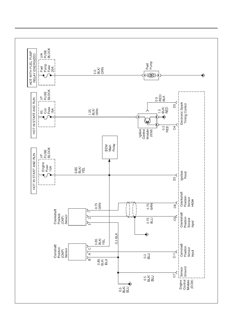
X22SE 2.2L ENGINE DRIVEABILITY AND EMISSION
ENGINE CRANKS BUT WILL NOT RUN
D06RX099