Opel Frontera UE. Manual - part 703


  Index      Opel     Opel Frontera UE - service repair manual 1999-2001 year


Search            


Content   ..  701  702  703  704   ..


Opel Frontera UE. Manual - part 703


DRIVE SHAFT SYSTEM

4C–31

1. Using a soft drift, tap the outside of the bearing cup 

assembly to loosen snap ring.  Tap bearing only 
hard enough to break assembly away from snap 
ring.
Remove snap ring from yoke.  Turn joint over, tap 
bearing away from snap ring, then remove opposite 
snap ring.
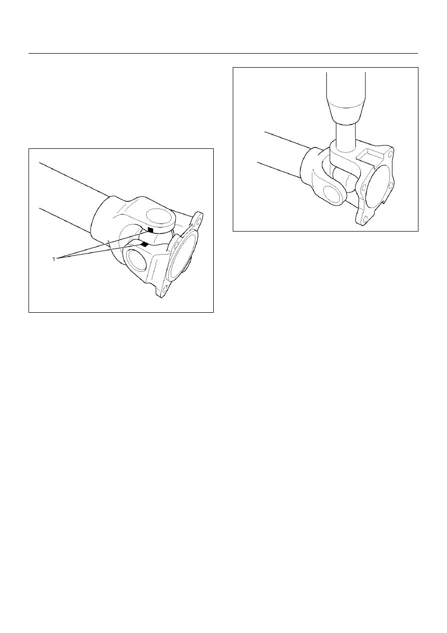
Apply alignment marks (1) on the yokes of the 
universal joint,  then remove snap ring.

401RW018

2. Set the yoke in the arbor press with a piece of tube 

stock beneath it.
Place a solid plug on the upper bearing assembly 
and press it through to release the lower bearing 
assembly.

401RW020

3. If the bearing assembly will not pull out by hand 

after pressing, tap the base of the lug near the 
bearing assembly to dislodge it.

4. To remove the opposite bearing, turn the yoke over 

and straighten the spider in the open hole.  Then 
carefully press on the end of the spider so the 
remaining bearing moves straight out of the bearing 
spider hole.  If the spider or bearing are cocked, the 
bearing will score the walls of the spider hole and 
ruin the yoke. 

5. Repeat this procedure on the remaining bearing to 

remove the spider from the yoke.

6. Make sure of proper position for reinstallation by 

applying setting marks, then remove spider .

4C–32

DRIVE SHAFT SYSTEM

Universal Joint Disassembly (Double Cardan Type)

401RW073

Legend

EndOFCallout

1. Using a soft drift, tap the outside of the bearing cup 

assembly to loosen snap ring. Tap bearing only hard 
enough to break assembly away from snap ring.

2. Remove snap ring from yoke. Turn joint over, tap 

bearing away from snap ring, then remove opposite 
snap ring.

401RW084

(1) Ball Stud Tube Yoke
(2) Cross and Bearing Kit
(3) Coupling Yoke

(4) Spring
(5) Cross and Bearing Kit
(6) Flange Yoke

DRIVE SHAFT SYSTEM

4C–33

3. Remove all snap rings from the yoke in similar 

manner.

4. Set the outboard side of the center yoke in the arbor 

press with a piece of tube stock beneath it. Place a 
solid plug on the upper bearing cup assembly and 
press it through to release the lower bearing cup 
assembly.
Press the center bearing cup assembly partially 
from the outboard side of the center yoke - enough 
to grasp the bearing cup by vise jaws.
Do not press the bearing cup assembly completely 
through.

401RW083

5. Grasp the protruding bearing cup assembly by vise 

jaws. Tap the tube yoke with a mallet and drift to 
dislodge the bearing cup assembly from the yoke 
hole.

401RW082

6. Flip the assembly and repeat steps 4 and 5 for 

removing the opposite side bearing cup assembly. 
This will allow removal of the cross centering kit 
assembly and spring.
Do not disassemble centering kit.

401RW068

7. Press the remaining bearing cup assemblies out on 

the other cross as described above to complete 
disassembly.

NOTE:  Tap in the center of the “H" yoke. Never strike 
the yokes at the bearing cup assembly holes because 
the snap ring grooves may collapse and make 
reassembly impossible. 

Inspection and Repair

Make necessary correction or parts replacement if 
wear, damage, corrosion or any other abnormal 
condition is found through inspection.

NOTE:  When any part of the journal assembly (spider, 
needle roller bearing) requires replacement, be sure to 
replace the entire assembly.
Check the following parts for wear, damage, noise or 
any other abnormal conditions.

1. Spider

2. Needle roller bearing

3. Yoke

4. Flange

5. Boot

4C–34

DRIVE SHAFT SYSTEM

Spider pin for wear

Spider pin should be smooth and free from fretting or 
galling.  Visible signs of needle presence is normal, but 
wear should not be felt.

401RW038

Propeller shaft runout

Support the propeller shaft on V-blocks (2) and check 
for runout by holding the probe of a dial indicator (1) in 
contact with the shaft.

Static runout limit:

0.13mm (0.005in)

TIR on the neck of the slip tube shaft (with a 
boot).

0.25mm (0.010in)

TIR on the ends of the tubing 3 inch from the 
welds.

0.38mm (0.015in)

TIR at the linear center of the tube.

0.38mm (0.015in)

TIR for the full length of tube with 30" or less of 
tubing.

(TIR : Total Indicator Reading)

401RS027

Spline

The nylon-coated spline should be free from nicks and 
dings and the underlying steel spline should not be 
visible.
After cleaning the nylon coating spline, the coating 
should exhibit only a slight indication of wear.
Grease volume is approximately 10 grams of grease in 
total.  Grease should be evenly applied to both the 
female and  the male slip splines using a small brush.  
After assembly of the slip joint, the sliding joint should 
be fully worked from the full collapsed to the full 
extended position.

Play in the universal joint

Limit:Less than0.15mm (0.006 in)

401RW023


Content   ..  701  702  703  704   ..