Opel Frontera UE. Manual - part 644


  Index      Opel     Opel Frontera UE - service repair manual 1999-2001 year


Search            


Content   ..  642  643  644  645   ..


Opel Frontera UE. Manual - part 644


HEATING, VENTILATION AND AIR CONDITIONING (HVAC)

1A–133

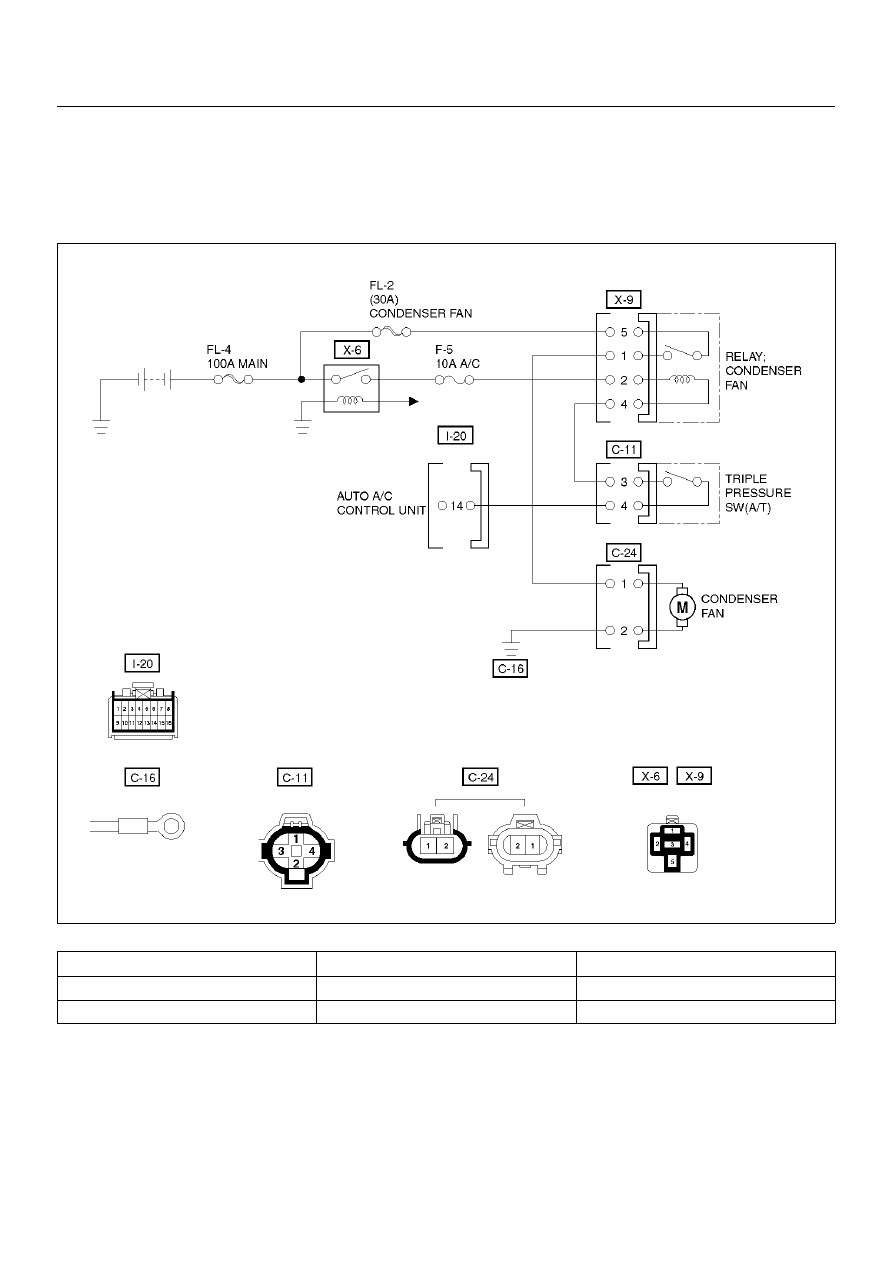
Condenser Fan Diagnosis

While the air conditioning is ON, the cycling switch in
the triple pressure switch senses the refrigerant
pressure, and activates the condenser fan to improve
the cooling capacity of the condenser when the
refrigerant pressure exceeds a set pressure value. The

condenser fan stops when the air conditioning is turned
“OFF" or when the pressure goes down below the set
pressure value.

D08RX255

Condition

Possible cause

Correction

Condenser fan does not run.

Refer to Chart A

Condenser fan does not stop.

Refer to Chart B

1A–134

HEATING, VENTILATION AND AIR CONDITIONING (HVAC)

Chart “A" Condenser Fan Does Not Run

Step

Action

Value(s)

Yes

No

Is the fusible link No.FL–2 normal?

Go to Step 2

Replace the 

fusible link wire

Is the fuse No.F–5 normal?

Go to Step 3

Replace the 

fuse

Is the heater relay (No.X–6) and condenser fan relay
(No.X–9) normal?

Go to Step 4

Replace the 

relay

1. Disconnect the condenser fan motor connector

No.C–24.

2. Connect the motor side connector terminal

No.C24–1 to the battery positive terminal and
No.C24–2 to the battery negative terminal.

Dose the fan operate?

Go to Step 6

Go to Step 5

Repair or replace the condenser fan motor.
Is the action complete?

Go to Step 4

Is there continuity between the harness side
connector terminal No.C24–2 and ground (C–16)?

Go to Step 8

Go to Step 7

Repair an open circuit between terminal No.C24–2
and No.C–16.
Is the action complete?

Go to Step 6

Is there continuity between the harness side
connector terminal No.C24–1 and No.X9–1?

Go to Step 10

Go to Step 9

Repair an open circuit between terminal No.C24–1
and No.X9–1.
Is the action complete?

Verify repair

10 

Is the battery voltage applied between the harness
side connector terminal No.X9–5 and ground?

Go to Step 12

Go to Step 11

11 

Repair an open circuit between terminal No.X9–5 and
No.FL–2.
Is the action complete?  

Go to Step 10

12 

Is the battery voltage applied between the harness
side connector terminal No.C11–3 and ground?

Go to Step 14

Go to Step 13

13 

Repair an open circuit between terminal No.X9–4 and
No.C11–3.
Is the action complete?

Go to Step 12

14 

Is there continuity between the harness side
connector terminal No.C11–4 and No.I20–14?

Go to Step 16

Go to Step 15

15 

Repair an open circuit between terminal No.C11–4
and No.I20–14.
Is the action complete?

Verify repair

16  Connect the harness side connector terminal

No.C24–1 to the battery terminal and No.C24–2 to the
battery negative terminal.
Is the battery voltage between the pressure switch
side connector terminal No.C24–4 and ground?

Go to Step 18

Go to Step 17

17 

Replace the triple pressure switch.
Is the action complete?

Verify repair

18 

Replace the auto air conditioner control unit.
Is the action complete?

Verify repair

HEATING, VENTILATION AND AIR CONDITIONING (HVAC)

1A–135

Chart “B" Condenser Fan Does Not Stop

Step

Action

Value(s)

Yes

No

1. Turn on the ignition switch “ON" (the engine is

run).

2. Air conditioning switch “OFF".

3. Disconnect the triple pressure switch.

Does the condenser fan stop?

Go to Step 2

Go to Step 3

Replace the triple pressure switch.
Is the action complete?

Verify repair

Disconnect the relay.
Is there continuity between the harness side
connector terminal No.X9–4 and ground?

Go to Step 4

Go to Step 5

Repair short circuit between terminal No.X9–4 and
No.C11–3.
Is the action complete?

Verify repair

Replace the relay condenser fan.
Is the action complete?

Verify repair

1A–136

HEATING, VENTILATION AND AIR CONDITIONING (HVAC)

Individual Inspection

In Car Sensor

1. Disconnect the in car sensor connector (I–4).

2. Measure resistance between the in car sensor side

terminal     No.I4–3 and No.I4–4.

865RX007

Sun Sensor

1. Disconnect the sun sensor connector (I–50).

2. Measure the current value on the sun sensor when

placed it     approximately 15 cm away from 60W
incandescent lamp.

C01RX013


Content   ..  642  643  644  645   ..