Opel Frontera UE. Manual - part 637


  Index      Opel     Opel Frontera UE - service repair manual 1999-2001 year


Search            


Content   ..  635  636  637  638   ..


Opel Frontera UE. Manual - part 637


HEATING, VENTILATION AND AIR CONDITIONING (HVAC)

1A–105

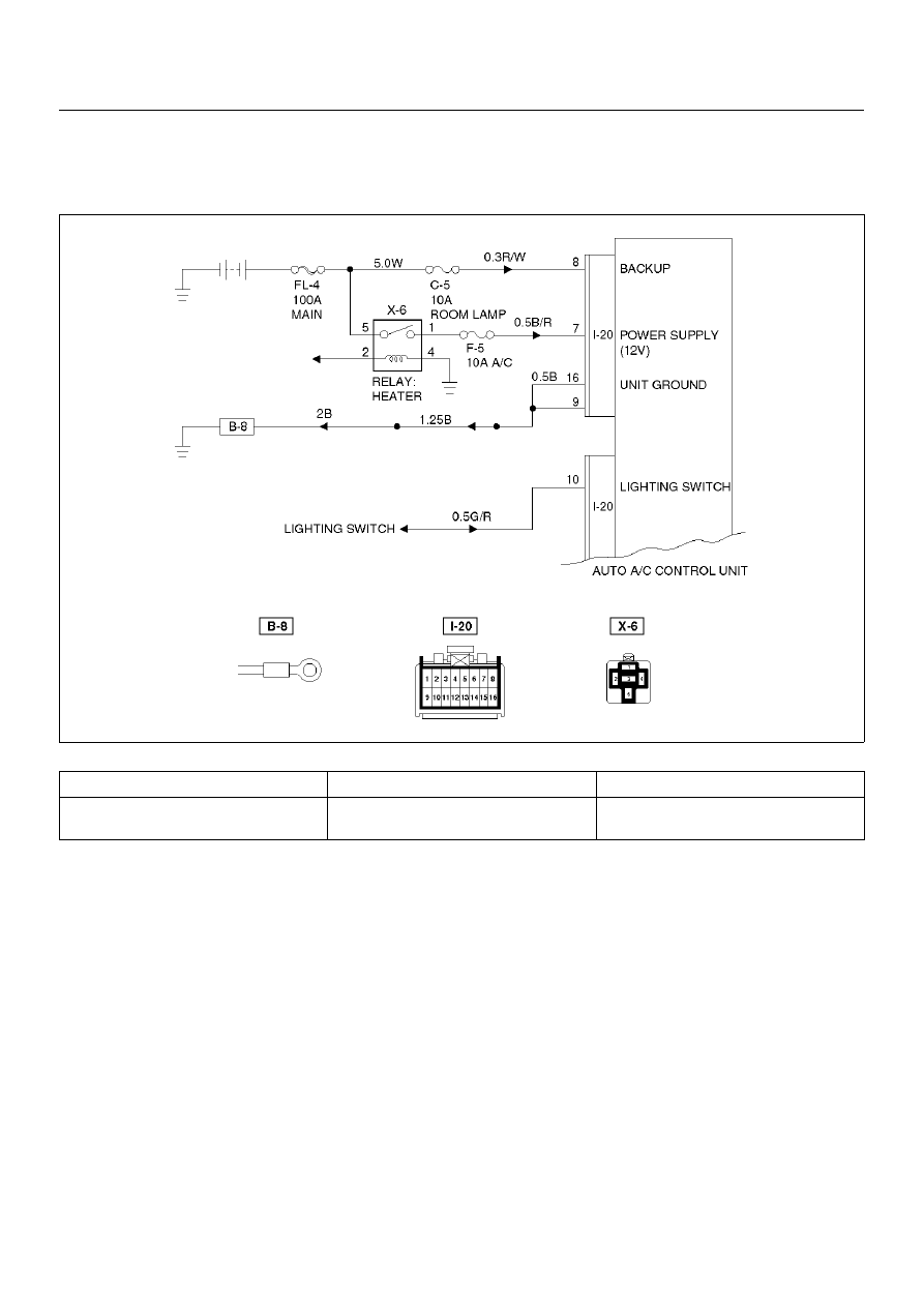
Auto Air Conditioner Control Unit Power Supply Diagnosis

This check is required because a trouble on the auto
amplifier (control unit) power supply circuit or grounding
circuit prevents accurate troubleshooting.

D08RX284

Condition

Possible cause

Correction

Power source does not supply to auto
air conditioner control unit.

Refer to Chart A

1A–106

HEATING, VENTILATION AND AIR CONDITIONING (HVAC)

Chart “A": Check of Auto Amplifier Power Supply System

Step

Action

Value(s)

Yes

No

Is the fuse C–5 normal?

Go to Step 2

Replace the 

fuse

Is the fuse F–5 normal?

Go to Step 3

Replace the 

fuse

Disconnect the auto A/C control unit connector I–20.   
Is the battery voltage applied between the harness
side connector terminal No.I20–8 and the ground?

Approx. 12V

Go to Step 5

Go to Step 4

Repair an open circuit between the fuse C–5 and
terminal No.I20–8.   
Is the action complete?

Go to Step 4

Is there continuity between the harness side
connector terminal No.I20–16 and the ground?

Go to Step 7

Go to Step 6

Repair an open circuit between terminal No.I20–16
and the ground No.B–8.
Is the action complete?

Go to Step 5

Is there continuity between the harness side
connector terminal No.I20–9 and the ground?

Go to Step 9

Go to Step 8

Repair an open circuit between terminal No.I20–9 and
the ground No.B–8.
Is the action complete?

Go to Step 7

Turn the lighting switch on.
Is the battery voltage applied between the harness
side connector terminal No.I20–10 and the ground?

Approx. 12V

Go to Step 11

Go to Step 10

10 

Repair an open circuit between the lighting switch and
terminal No.I20–10.
Is the action complete?

Go to Step 9

11 

Turn the starter switch on.
Is the battery voltage applied between the harness
side connector terminal No.I20–7 and the ground?

Approx. 12V

Go to Step 12

12 

Repair an open circuit between the fuse F–5 and
terminal No.I20–7.
Is the action complete?

Verify repair

HEATING, VENTILATION AND AIR CONDITIONING (HVAC)

1A–107

Performance and Movement checklist for Automatic Air Conditioner Related
Parts

Start the engine, and when the engine coolant reached
50

°

C check performance and movement of the related

parts according the following checklist.

Performance Check Using the Manual Switch

No.

Item

Checking Approach

Acceptance criteria

Condition

Operation

1

Blowing
temperature (check
movement of air
mix door)

Auto switch must be
turned on    (FAN-AUTO
MODE-AUTO)

1. Select FC for the

setup temperature.

2. Select FH for the

setup temperature.

 Then, select the

MAX Control.

1. Cold air shall be blown out.

2. Hot air shall be blown out.

2

Airflow volume
(check movement
of the mode door)

Set temperature to
25.0

°

C.

1. Turn the fan knob

off.

2. Turn the fan knob

from LOW to HI.

1. The fan shall be stopped, thus

stopping air blow, too.

2. Airflow volume shall change from

LOW to HI.

3

Blowing
temperature
(check movement
of the mode door)

Set temperature to
25.0

°

C.    Set the fan

knob to HI.

Press the mode switch
to change the blow port
mode sequentially from
the VENT through
BI-LEVEL, FOOT up to
DEF.

LED corresponding to each mode
shall be turned on and the blow port
mode shall be switched smoothly.

4

The interior/outside
air switching mode
(check movement
of intake door)

Set temperature to
25.0

°

C.

Turn the LED off using
the interior/outside air
switch (this introduces
the outside air intake
mode).  Then, the set
fan knob to HI and
press the interior/
outside switch to turn
on the LED.

The LED indication shall be switched
from OFF to ON accompanying a
change in air blowing sound.

5

Compressor

Set the temperature to
18.0

°

C (FC).  (Outside

air temperature is 0

°

C

or above and interior
temperature at ordinary
temperature.)

Press the “OFF" switch.

1. Press the Auto

switch.

2. Press the Air

Conditioner switch.

1. As the fan knob is set to the Auto

position, the A/C switch LED
shall come on and the
compressor shall be turned on.

2. As the A/C LED comes off, the

compressor shall be turned off.

1A–108

HEATING, VENTILATION AND AIR CONDITIONING (HVAC)

Check of Auto Function

No.

Item

Checking Approach

Acceptance criteria

Condition

Operation

1

Auto function

FAN KNOB “AUTO"

MODE SW “AUTO"

Select FC for the 
temperature.

The LED shall come on. 
Cold air shall be blown out.
The following LEDs shall come on:

• Blow port mode:

• Intake mode

• Fan speed: MAX

Hi

• A/C

Change the 
temperature 
gradually starting 
with 18

°

C up to 

32

°

C.

The following phenomena shall be
recognized.

• Temperature of blown air: Cold air is

changed to hot air.

• Change in the air flow volume.

• The blow port mode LED indication

changes in the following sequence:

Select FH for the 
temperature.

Cold air shall be blown out. The
following LEDs shall come on.

• Blow port mode:

• Fan speed: Max.


Content   ..  635  636  637  638   ..