Opel Frontera UE. Manual - part 627


  Index      Opel     Opel Frontera UE - service repair manual 1999-2001 year


Search            


Content   ..  625  626  627  628   ..


Opel Frontera UE. Manual - part 627


HEATING, VENTILATION AND AIR CONDITIONING (HVAC)

1A–65

• Lift to remove the upper case.

874RY00027

8. Remove evaporator core.

874RY00028

9. Remove expansion valve.

• Tear off the insulator carefully.

• Remove the sensor fixing clip.

• Use a back-up wrench when disconnecting all

refrigerant pipes.

Installation

To install, follow the removal steps in the reverse order,
noting the following points:

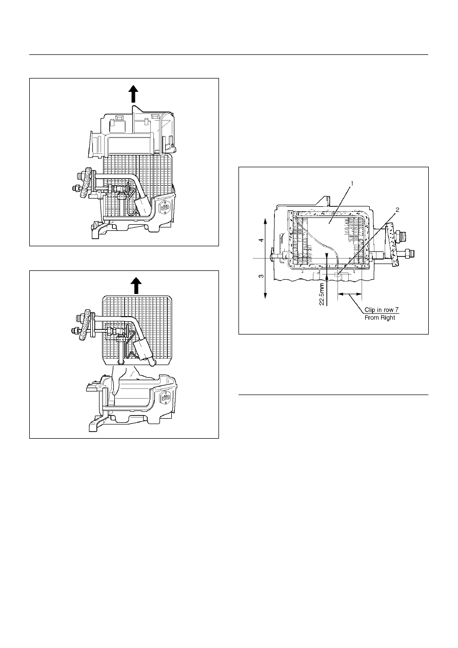
1. The sensor is installed on the core with the clip.

2. The sensor must not interfere with the evaporator

core.

3. When installing the new evaporator core, install the

thermo sensor to the evaporator core specified
position with the clip in the illustration.   

874RX014

EndOFCallout

4. O-rings cannot be reused. Always replace with new

ones.

5. Be sure to apply new compressor oil to the O-rings

when connecting lines.

6. Be sure to install the sensor and the insulator on the

place where they were before.

7. To install a new evaporator core, add 50cc (1.7 fl.

oz.) of new compressor oil to the new core.

8. Tighten the refrigerant lines to the specified torque.

Refer to Main Data and Specifications for Torque
Specifications in this section.       

9. Apply an adhesive to the parting face of the lining

when assembling the evaporator assembly.

Legend

(1) Evaporator Core
(2) Thermo Sensor
(3) Lower Case
(4) Upper Case

1A–66

HEATING, VENTILATION AND AIR CONDITIONING (HVAC)

Refrigerant Line

Refrigerant Line and Associated Parts

852RY00032

EndOFCallout

Removal

1. Disconnect the battery ground cable.

2. Discharge and recover refrigerant.

• Refer to Refrigerant Recovery in this section.

3. Remove radiator grille.

4. Remove clip and clamp.

5. Disconnect liquid line (High-pressure pipe).

6. Disconnect suction line (Low-pressure pipe) using a

back-up wrench.

7. Disconnect suction line (Low-pressure hose) using

a back-up wrench.

8. Disconnect discharge line (High-pressure hose)

using a back-up wrench.

• Use a backup wrench when disconnecting and

reconnecting the refrigerant lines.

• When removing the refrigerant line connecting

part, the connecting part should immediately be

Legend

(1) Clip and Clamp
(2) Liquid Line (High-Pressure Pipe)

(3) Radiator Grille
(4) Discharge Line (High-Pressure Hose)
(5) Suction Line (Low-Pressure Pipe)

HEATING, VENTILATION AND AIR CONDITIONING (HVAC)

1A–67

plugged or capped to prevent foreign matter from
being mixed into the line.

Installation

To install, follow the removal steps in the reverse order,
noting the following point:

1. O-rings cannot be reused. Always replace with new

ones. 

2. Be sure to apply new compressor oil to the O-rings

when connecting lines.   

3. Tighten the refrigerant line to the specified torque.

Refer to Main Data and Specifications for Torque
Specifications in this section.

1A–68

HEATING, VENTILATION AND AIR CONDITIONING (HVAC)

Main Data And Specifications

General Specifications

Heater Unit

Temperature control

Reheat air mix system

Capacity

3,700 Kcal./hr.

Air flow

280 m

3

/h

HEATER CORE

Type

AUTO A/C

Plate and corrugate-fin type

MANU A/C

Fin and tube type

Element dimension

MANU A/C

161 mm (6.3) 

× 

163 mm (6.4 in.) 

×

 45 mm (1.8 in.)

AUTO A/C

171 mm (6.7) 

× 

161 mm (6.3 in.) 

×

 25 mm (1 in.)

Radiating area

MANU A/C

Approx. 2.1 m

2

AUTO A/C

Approx. 1.3 m

2

EVAPORATOR ASSEMBLY

Capacity

AUTO A/C

4,100 Kcal./hr.

MANU A/C

4,200 Kcal./hr.

Air flow

AUTO A/C

430 m

3

/hr

MANU A/C

470 m

3

/hr

EVAPORATOR CORE

Type

Al-laminate louver fin type

Element dimension

235 mm (9.3 in.) 

×

 224 mm (8.8 in.) 

×

 60 mm (2.4 in.)

EXPANSION VALVE

Type

Internal pressure equalizer type

THERMOSTAT SWITCH

Type

Electronic thermostat

OFF: Below 0.5 

±

 0.5 

°

C (32.9 

±

 0.9 

°

F)

ON: Above 4.5 

±

 0.5 

°

C (40.1 

±

 0.9 

°

F)

CONDENSER

Type

Parallel flow type

Radiation performance

9,400 Kcal./hr

RECEIVER/DRIER

Type

Assembly includes sight glass with dual (triple) pressure 
switch (V6) or pressure sensor (L4)

Internal volume

300 cc (10 fl.oz.)


Content   ..  625  626  627  628   ..