Opel Frontera UE. Manual - part 592
RESTRAINT CONTROL SYSTEM
9J1–13
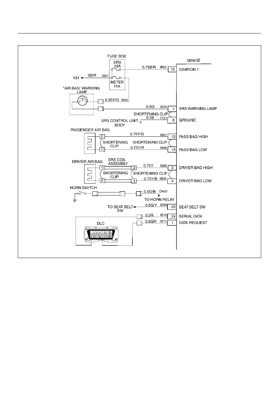
Chart C “AIR BAG" Warning Lamp Does Not Comes “ON" Steady
D09RX002
Circuit Description:
When the ignition switch is first turned “ON", “ignition 1"
voltage is applied from the “METER" fuse to the “AIR
BAG" warning lamp which is connected to
“Supplemental Restraint System (SRS) warning lamp",
terminal “7". The “SRS" fuse apply system voltage to
the “ignition 1" inputs, terminals “12". The Sensing and
Diagnostic Module (SDM) responds by flashing the “AIR
BAG" warning lamp seven times. If “ignition 1" voltage
is more than 16 volts, the “AIR BAG" warning lamp will
be still “OFF" solid with no DTCs set.
Chart Test Description:
Number(s) below refer to step number(s) on the
diagnostic chart:
1. This test decides whether power is available to SDM
warning lamp power feed circuit.
2. This test determines whether the voltage is present in
the warning lamp circuit.
3. This test determines if the malfunction is in the
instrument cluster.
4. This test checks for open in the warning lamp
circuitry.
5. This test isolates the IB04–GREEN circuit and checks
for a short in the IB04–GREEN circuit to B+.
8. This test checks for a short from the SDM warning
lamp power feed circuit to ground.
9. This test determines whether the short to ground is
due to a short in the wiring.