Index Opel Opel Frontera UE - service repair manual 1999-2001 year
Search
Content .. 483 484 485 486 ..
Opel Frontera UE. Manual - part 485
8D–80
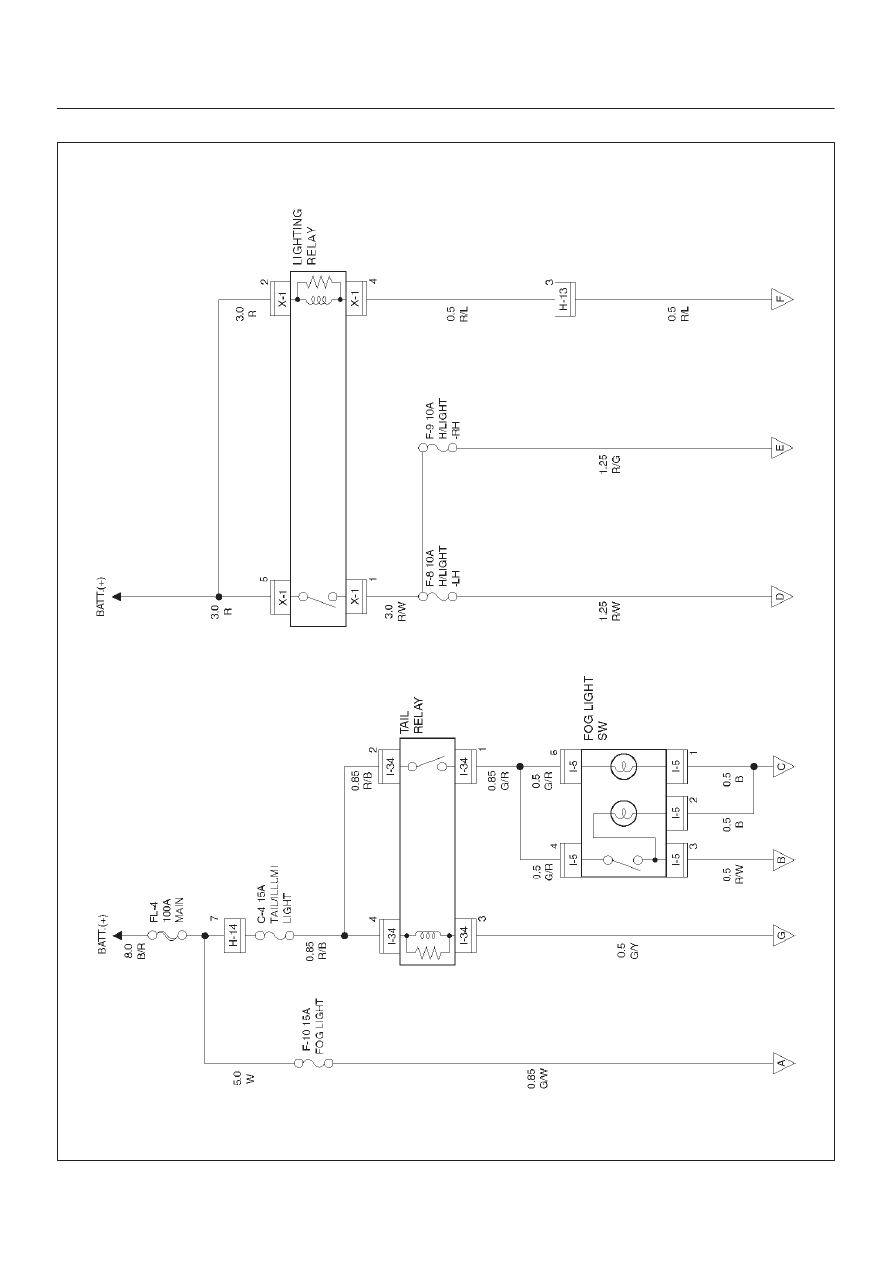
WIRING SYSTEM
Circuit Diagram–1
D08RX192