Opel Frontera UE. Manual - part 439


  Index      Opel     Opel Frontera UE - service repair manual 1999-2001 year


Search            


Content   ..  437  438  439  440   ..


Opel Frontera UE. Manual - part 439


MANUAL TRANSMISSION

7B–29

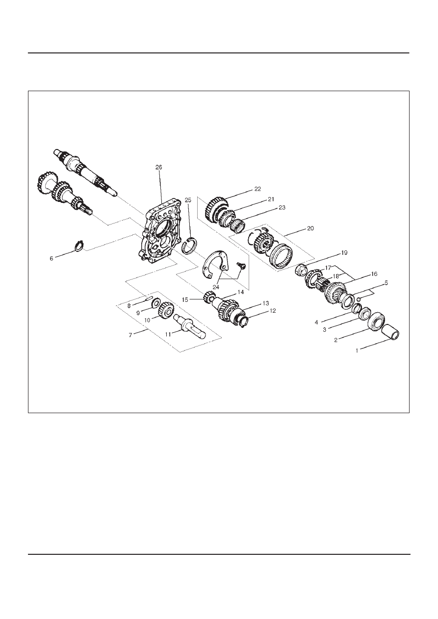
Reverse Gear and 5th Gear (MUA)

Disassembled View

226RW213

Legend

(1) Oil Seal Collar
(2) Ball Bearing
(3) Retainer
(4) Thrust Plate
(5) Thrust Washer and Lock Ball
(6) Reverse Idler Gear Snap Ring
(7) Reverse Idler Gear Assembly
(8) Idle Shaft Pin
(9) Thrust Washer

(10) Reverse Idler Gear

(11) Reverse Idler Shaft

(12) Bearing Snap Ring
(13) Ball Bearing

(14) Counter 5th Gear
(15) Counter Reverse Gear
(16) 5th Gear
(17) 5th Block Ring
(18) Needle Bearing
(19) Mainshaft Nut
(20) Rev–5th Synchronizer Assembly
(21) Reverse Block Ring
(22) Reverse Gear
(23) Needle Baring
(24) Bearing Plate and Screw
(25) Bearing Snap Ring
(26) Intermediate Plate

7B–30

MANUAL TRANSMISSION

Disassembly

1. Set the retaining ring remover 5–8840–2158–0 and

puller 5–8840–2027–0 to the retainer(3) and the
mainshaft end. 

262RW079

2. Remove the retainer(3) together with the bearing(2)

and the oil seal collar(1). 
The universal puller may be used in place of the
retaining ring remover.

3. Remove thrust plate(4) and thrust washer and lock

ball(5).

4. Use a pair of snap ring pliers to remove reverse idler

gear snap ring(6).

226RS004

5. Remove the reverse idler gear assembly(7) from the

intermediate plate(26).

226RS005

6. Remove idle shaft pin(8), thrust washer(9), reverse

idler gear(10), and reverse idler shaft(11).

7. Use a pair of snap ring pliers to remove the snap

ring(12).

8. Attach the bearing remover to the counter gear shaft.

Use the bearing remover to remove the ball
bearing(13) and the counter 5th gear(14).

226RS006

9. Remove counter reverse gear(15).

MANUAL TRANSMISSION

7B–31

10. Remove 5th gear(16), 5th block ring(17), and needle

bearing (2 piece type) (18).

226RS007

11. Attach the holding fixture 5–8840–2160–0 and base

5–8840–0003–0 to the mainshaft and the counter
gear.

226RW212

12. Engage the 3rd–4th synchronizer with the 3rd gear.

Engage the 1st–2nd synchronizer with the 1st gear.

226RW210

Use the mainshaft nut wrench 5–8840–2156–0 to
remove the mainshaft nut(19).

226RW211

7B–32

MANUAL TRANSMISSION

13. Use pry bars between the reverse gear(22) and

bearing plate(24) to remove the Rev–5th
synchronizer assembly(20) together with reverse
block ring(21) and reverse gear(22).

226RS010

14. Remove needle bearing(23).
15. Use the torx bit wrench 5–8840–0047–0(T45) to

remove the bearing plate and screw(24) from the
intermediate plate.

220RW137

16. Use the snap ring pliers(1) to remove the mainshaft

bearing snap ring(29).

226RS011

17. Hold the snap ring open with the pliers.

Push the intermediate plate(26) toward the rear of the
transmission to remove it.
The bearing snap ring(25) will come free.

Inspection and Repair

Refer to Top Gear Shaft, Main Gear Shaft, and Counter
Gear in this section for inspection and repair.

Reassembly

1. Mesh the counter gear with the mainshaft assembly.

Install the holding fixture 5–8840–2160–0 and base
5–8840–0003–0 to the mainshaft and the counter
gear.

226RW212


Content   ..  437  438  439  440   ..