Opel Frontera UE. Manual - part 416


  Index      Opel     Opel Frontera UE - service repair manual 1999-2001 year


Search            


Content   ..  414  415  416  417   ..


Opel Frontera UE. Manual - part 416


7A1–12 TRANSMISSION CONTROL SYSTEM (4L30–E)
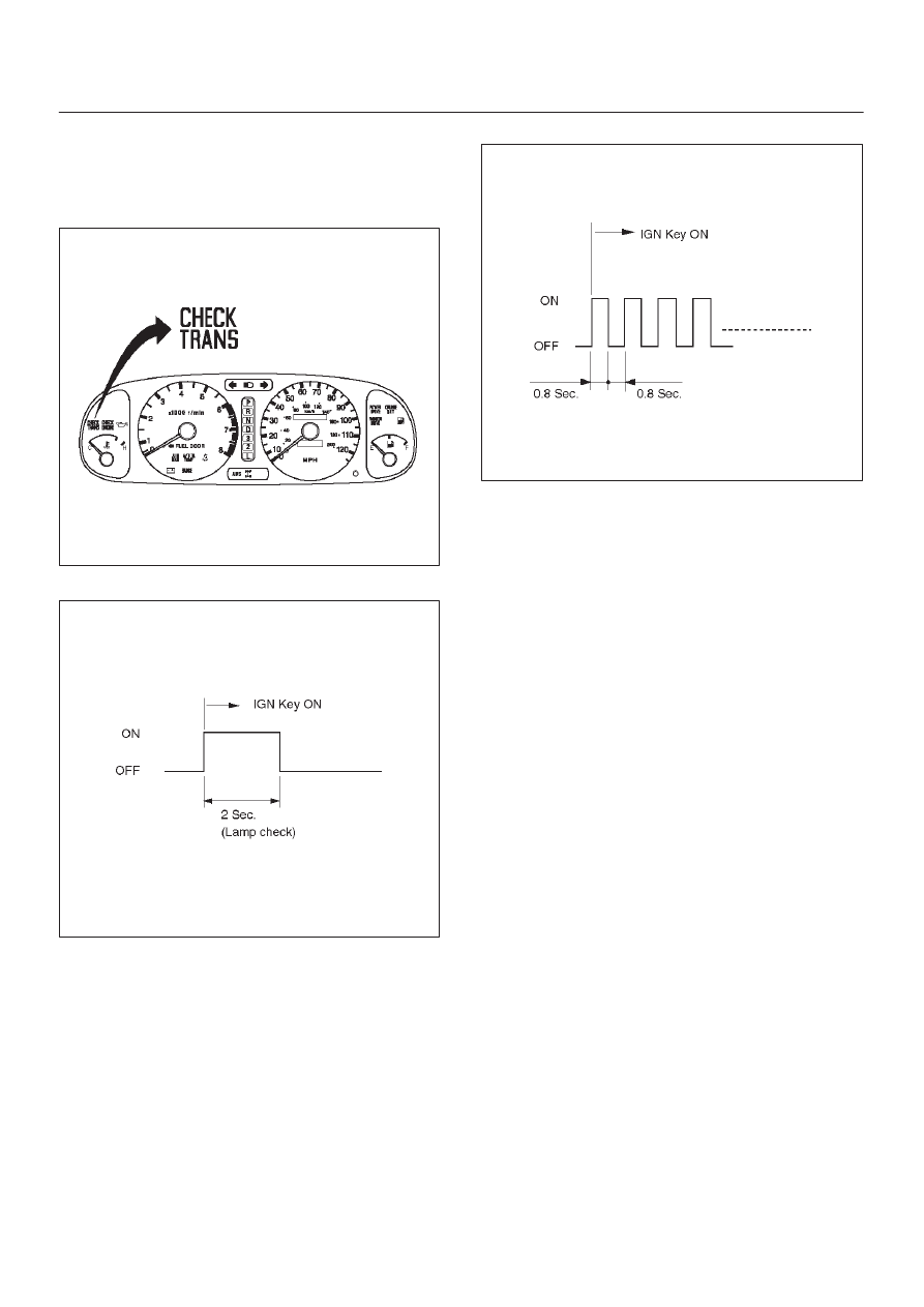
“Check Trans” Check

1. Indicator is ON during 2 seconds at ignition (or when

the engine is cranked) but it is OFF after the engine
starts. The indicator is working normally GOTO
DIAGNOSTIC CHECK.

821RW105

Normal

C07RW047

2. Indicator is flashing and the flash is 0.8 seconds ON

and 0.8 seconds OFF always when ignition is on
(engine cranked or not). This means that there is a
malfunction. GOTO DIAGNOSTIC CHECK.

Abnormal

C07RX009

3. Indicator is staying ON always when Ignition is ON.

1. This means that connection between the lamp

and the PCM is shorted to ground.

2. Verify if instrument panel terminal 6 of connector

I–1 is shorted to ground.

3. Verify if the PCM connector C1 (RED) terminal

A14 is shorted to ground.

4. Verify that the instrument panel terminal 12 of

connector I–1 is connected to battery.

5. IF problem solved: GOTO CHECK TRANS

INDICATOR.

NO:Replace Powertrain Control Module (PCM).

4. Indicator is staying OFF with the ignition ON (engine

OFF).
1. This means that connection between the lamp

and the PCM is shorted to battery or opened.

2. Verify if instrument panel terminal 6 of connector

I–1 is shorted to battery or open.

3. Verify if the PCM connector C1 (RED) terminal

A14 is shorted to battery or open.

4. Verify that the instrument panel terminal 12 of

connector I–1 is connected to battery. If not,
check the fuses and the connections voltage.

5. IF problem solved: GOTO CHECK TRANS

INDICATOR.

NO: Replace Powertrain Control Module (PCM).

TRANSMISSION CONTROL SYSTEM (4L30–E)

7A1–13

D07RX015

Tech 2 OBD II Connection

In order to access OBD II Powertrain Control Module
(PCM) data, use of the Tech 2 scan tool kit (7000086) is
required.

1. The electronic diagnosis equipment is composed of:

1. Tech 2 hand–held scan tool unit (7000057) and

DLC cable (3000095).

901RW176

2. SAE 16/19 Pin Adapter (3000098)(1), RS232

Loop Back Connector (3000112)(2), and
PCMCIA Card (3000117)(3).

F07RW033

7A1–14 TRANSMISSION CONTROL SYSTEM (4L30–E)

2. Connecting the Tech 2

901RW180

Legend

(1) PCMCIA Card
(2) RS 232 Loop Back Connector

(3) SAE 16/19 Adapter
(4) DLC Cable
(5) Tech 2

TRANSMISSION CONTROL SYSTEM (4L30–E)

7A1–15

D

Before operating the Isuzu PCMCIA card with the
Tech 2, the following steps must be performed:

1. The Isuzu 99 System PCMCIA card (1) inserts

into the Tech 2 (5).

2. Connect the SAE 16/19 adapter (3) to the DLC

cable (4).

3. Connect the DLC cable to the Tech 2 (5)

4. Mark sure the vehicle ignition is off.

5. Connect the Tech 2 SAE 16/19 adapter to the

vehicle DLC.

810RW317

6. The vehicle ignition turns on.

7. Verify the Tech 2 power up display.

060RW009

NOTE: The RS232 Loop back connector is only to use for
diagnosis of Tech 2 and refer to user guide of the Tech 2.

8. The power up screen is displayed when you

power up the tester with the Isuzu systems
PCMCIA card. Follow the operating procedure
below.

060RX004


Content   ..  414  415  416  417   ..