Opel Frontera UE. Manual - part 381


  Index      Opel     Opel Frontera UE - service repair manual 1999-2001 year


Search            


Content   ..  379  380  381  382   ..


Opel Frontera UE. Manual - part 381


6E2–330

6VD1 3.2L ENGINE DRIVEABILITY AND EMISSIONS

loads, causing the spark to run too hot.  Another possible
cause is an excessively lean fuel mixture.

TS23992

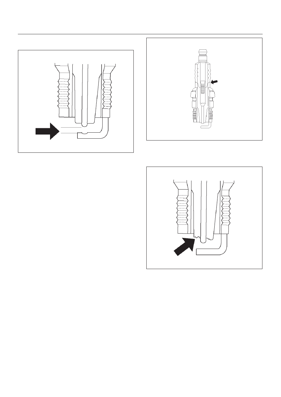
Low or high spark plug installation torque or improper
seating can result in the spark plug running too hot and
can cause excessive center electrode wear.  The plug
and the cylinder head seats must be in good contact for
proper heat transfer and spark plug cooling.  Dirty or
damaged threads in the head or on the spark plug can
keep it from seating even though the proper torque is
applied.  Once spark plugs are properly seated, tighten
them to the torque shown in the Specifications Table.  Low
torque may result in poor contact of the seats due to a
loose spark plug.  Overtightening may cause the spark
plug shell to be stretched and will result in poor contact
between the seats.  In extreme cases,  exhaust blow-by
and damage beyond simple gap wear may occur.
Cracked or broken insulators may be the result of
improper installation, damage during spark plug
re-gapping, or heat shock to the insulator material.  Upper
insulators can be broken when a poorly fitting tool is used
during installation or removal, when the spark plug is hit
from the outside, or is dropped on a hard surface. Cracks
in the upper insulator may be inside the shell and not
visible. Also, the breakage may not cause problems until
oil or moisture penetrates the crack later.

TS23994

A broken or cracked lower insulator tip (around the center
electrode) may result from damage during re-gapping or
from “heat shock” (spark plug suddenly operating too
hot).

TS23993

D

Damage during re-gapping can happen if the gapping
tool is pushed against the center electrode or the
insulator around it, causing the insulator to crack.
When re-gapping a spark plug, make the adjustment
by bending only the ground side terminal, keeping the
tool clear of other parts.

D

”Heat shock” breakage in the lower insulator tip
generally occurs during several engine operating
conditions (high speeds or heavy loading) and may be
caused by over-advanced timing or low grade fuels.
Heat shock refers to a rapid increase in the tip
temperature that causes the insulator material to
crack.

Spark plugs with less than the recommended amount of
service can sometimes be cleaned and re-gapped , then
returned to service.  However, if there is any doubt about
the serviceability of a spark plug, replace it.  Spark plugs
with cracked or broken insulators should always be
replaced.

6E2–331

6VD1 3.2L ENGINE DRIVEABILITY AND EMISSIONS

A/C Clutch Diagnosis

A/C Clutch Circuit Operation

A 12-volt signal is supplied to the A/C request input of the
PCM when the A/C is selected through the A/C control
switch.
The A/C compressor clutch relay is controlled through the
PCM.  This allows the PCM to modify the idle air control
position prior to the A/C clutch engagement for better idle
quality.  If the engine operating conditions are within their
specified calibrated acceptable ranges, the PCM will
enable the A/C compressor relay.  This is done by
providing a ground path for the A/C relay coil within the
PCM.  When the A/C compressor relay is enabled,
battery voltage is supplied to the compressor clutch coil.
The PCM will enable the A/C compressor clutch
whenever the engine is running and the A/C has been
requested.  The PCM will not enable the A/C compressor
clutch if any of the following conditions are met:

D

The throttle is greater than  90%.

D

The engine speed is greater than 6315 RPM.

D

The ECT is greater than 119

°

C (246

°

F).

D

The IAT is less than 5

°

C (41

°

F).

D

The throttle is more than 80% open.

A/C Clutch Circuit Purpose

The A/C compressor operation is controlled by the
powertrain control module (PCM) for the following
reasons:

D

It improvises idle quality during compressor clutch
engagement.

D

It improvises wide open throttle (WOT) performance.

D

It provides A/C compressor protection from operation
with incorrect refrigerant pressures.

The A/C electrical system consists of the following
components:

D

The A/C control head.

D

The A/C refrigerant pressure switches.

D

The A/C compressor clutch.

D

The A/C compressor clutch relay.

D

The PCM.

A/C Request Signal

This signal tells the PCM when the A/C mode is selected
at the A/C control head.  The PCM uses this to adjust the
idle speed before turning on the A/C clutch.  The A/C
compressor will be inoperative if this signal is not
available to the PCM.

Refer to 

A/C Clutch Circuit Diagnosis for A/C wiring

diagrams and diagnosis for A/C electrical system.

General Description (Evaporative
(EVAP) Emission System)

EVAP Emission Control System Purpose

The basic evaporative emission (EVAP) control system
used on all vehicles is the charcoal canister storage
method.  Gasoline vapors from the fuel tank flow into the
canister through the inlet labeled “TANK.” These vapors
are absorbed into the activated carbon (charcoal) storage
device (canister) in order to hold the vapors when the
vehicle is not operating.  The canister is purged by PCM
control when the engine coolant temperature is over 60

°

C

(140

°

F), the IAT reading is over 10

°

C (50

°

F),  and the

engine has been running.  Air is drawn into the canister
through the air inlet grid.  The air mixes with the vapor and
the mixture is drawn into the intake manifold.

EVAP Emission Control System Operation

The EVAP canister purge is controlled by a solenoid valve
that allows the manifold vacuum to purge the canister.
The powertrain control module (PCM) supplies a ground
to energize the solenoid valve (purge on).  The EVAP
purge solenoid control is pulse-width modulated (PWM)
(turned on and off several times a second).  The duty
cycle (pulse width) is determined by engine operating
conditions including load, throttle positron, coolant
temperature and ambient temperature.  The duty cycle is
calculated by the PCM.  The output is commanded when
the appropriate conditions have been met.  These
conditions are:

D

The engine is fully warmed up.

D

The engine has been running for a specified time.

D

The IAT reading is above 10

°

C (50

°

F).

Poor idle, stalling and poor driveability can be caused by:

D

A malfunctioning purge solenoid.

D

A damaged canister.

D

Hoses that are split, cracked, or not connected
properly.

General Description (Exhaust Gas
Recirculation (EGR) System)

EGR Purpose

The exhaust gas recirculation (EGR) system is use to
reduce emission levels of oxides of nitrogen (NOx).  NOx
emission levels are caused by a high combustion

6E2–332

6VD1 3.2L ENGINE DRIVEABILITY AND EMISSIONS

temperature.  The EGR system lowers the NOx emission
levels by decreasing the combustion temperature.

057RW002

Linear EGR Valve

The main element of the system is the linear EGR valve.
The EGR valve feeds small amounts of exhaust gas back
into the combustion chamber.  The fuel/air mixture will be
diluted and combustion temperatures reduced.

Linear EGR Control

The PCM monitors the EGR actual positron and adjusts
the pintle position accordingly.  The uses information from
the following sensors to control the pintle position:

D

Engine coolant temperature (ECT) sensor.

D

Throttle position (TP) sensor.

D

Mass air flow (MAF) sensor.

Linear EGR Valve Operation and Results
of Incorrect Operation

The linear EGR valve is designed to accurately supply
EGR to the engine independent of intake manifold
vacuum.  The valve controls EGR flow from the exhaust
to the intake manifold through an orifice with a PCM
controlled pintle.  During operation, the PCM controls
pintle position by monitoring the pintle position feedback
signal.   The feedback signal can be monitored with a Tech
2 as “Actual EGR Pos.” “Actual EGR Pos.” should always
be near the commanded EGR position (”Desired EGR
Pos.”).  If a problem with the EGR system will not allow the

PCM to control the pintle position properly, DTC P1404
will set.  The PCM also tests for EGR flow.
The linear EGR valve is usually activated under the
following conditions:

D

Warm engine operation.

D

Above-idle speed.

Too much EGR flow at idle, cruise or cold operation may
cause any of the following conditions to occur:

D

Engine stalls after a cold start.

D

Engine stalls at idle after deceleration.

D

Vehicle surges during cruise.

D

Rough idle.

Too little or no EGR flow may allow combustion
temperatures to get too high.  This could cause:

D

Spark knock (detonation).

D

Engine overheating.

D

Emission test failure.

D

Poor fuel economy.

0017

EGR Pintle Position Sensor

The PCM monitors the EGR valve pintle position input to
endure that the valve responds properly to  commands
from the PCM and to detect a fault if the pintle position
sensor and control circuits are open or shorted.  If the
PCM detects a pintle position signal voltage outside the
normal range of the pintle position sensor, or a signal
voltage that is not within a tolerance considered
acceptable for proper EGR system operation, the PCM
will set DTC P1404.

General Description (Positive
Crankcase Ventilation (PCV) System)

Crankcase Ventilation System Purpose

The crankcase ventilation system is use to consume
crankcase vapors in the combustion process instead of
venting them to the atmosphere.  Fresh air from the
throttle body is supplied to the crankcase and mixed with
blow-by gases.  This mixture is then passed through the

6E2–333

6VD1 3.2L ENGINE DRIVEABILITY AND EMISSIONS

positive crankcase ventilation (PCV) valve into the
common chamber.

Crankcase Ventilation System Operation

The primary control is through the positive crankcase
ventilation (PCV) valve.  The PCV valve meters the flow at
a rate that depends on the intake vacuum.  The PCV valve
restricts the flow when the inlet vacuum is highest.  In
addition, the PCV valve can seal the common chamber
off in case of sudden high pressure in the crankcase.

028RV002

While the engine is running, exhaust fuses and small
amounts of the fuel/air mixture escape past the piston
rings and enter the crankcase.  These gases are mixed
with clean air entering through a tube from the air intake
duct.

028RW002

During normal, part-throttle operation, the system is
designed to allow crankcase gases to flow through the
PCV valve into the throttle body to be consumed by
normal combustion.
A plugged valve or PCV hose may cause the following
conditions:

D

Rough idle.

D

Stalling of slow idle speed.

D

Oil leaks.

D

Sludge in the engine.

A leaking PCV hose would cause:

D

Rough idle.

D

Stalling.

D

High idle speed.


Content   ..  379  380  381  382   ..