Opel Frontera UE. Manual - part 321
6E2–90
6VD1 3.2L ENGINE DRIVEABILITY AND EMISSIONS
Manifold Absolute Pressure (MAP) Output Check
D06RX135
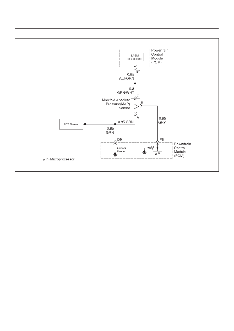
Circuit Description
The manifold absolute pressure (MAP) sensor measures
the changes in the intake MAP which result from engine
load (intake manifold vacuum) and engine speed
changes; and converts these into a voltage output. The
powertrain control module (PCM) sends a 5-volt
reference voltage to the MAP sensor. As the MAP
changes, the output voltage of the sensor also changes.
By monitoring the the sensor output voltage, the PCM
knows the MAP. A lower pressure (low voltage) output
voltage will be about 1-2 volts at idle. Higher pressure
(high voltage) output voltage will be about 4-4.8 volts at
wide open throttle. The MAP sensor is also used, under
certain conditions, to measure barometric pressure,
allowing the PCM to make adjustments for different
altitudes. The PCM uses the MAP sensor to diagnose
proper operation of the EGR system, in addition to other
functions.
Test Description
IMPORTANT:
Be sure to used the same diagnostic test
equipment for all measurements.
The number(s) below refer to the step number(s) on the
Diagnostic Chart.
1. Applying 34 kPa (10 Hg) vacuum to the MAP sensor
should cause the voltage to be 1.5-2.1 volts less
than the voltage at step 1. Upon applying vacuum
to the sensor, the change in voltage should be
instantaneous. A slow voltage change indicates a
faulty sensor.
IMPORTANT:
Make sure the electrical connector
remains securely fastened.
2. Disconnect the sensor from the bracket. Twist the
sensor with your hand to check for an intermittent
connection. Output changes greater than 0.10 volt
indicate a bad sensor.