Index Opel Opel Frontera UE - service repair manual 1999-2001 year
Search
Content .. 314 315 316 317 ..
Opel Frontera UE. Manual - part 316
6E2–70
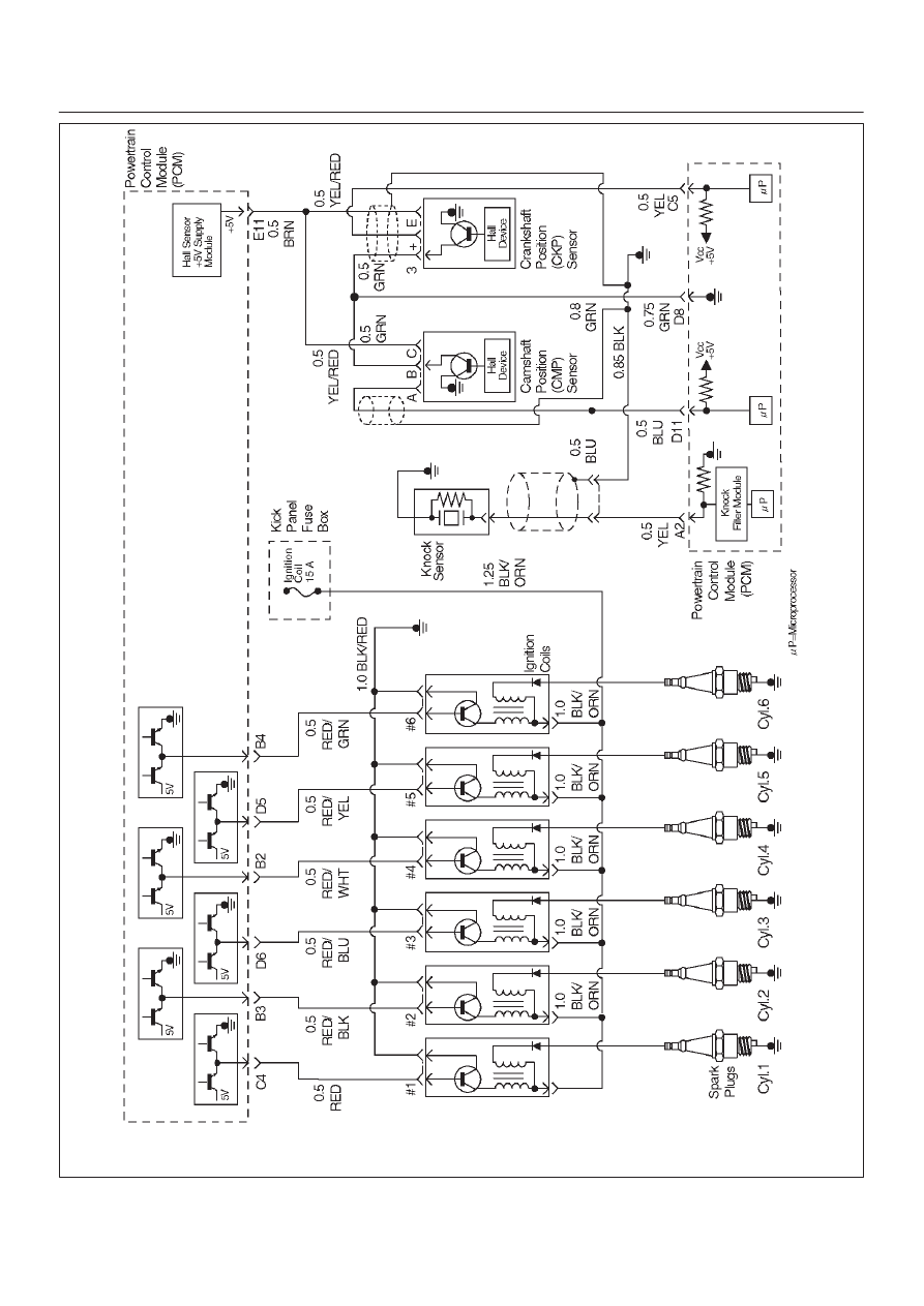
6VD1 3.2L ENGINE DRIVEABILITY AND EMISSIONS
D06RX146