Opel Frontera UE. Manual - part 298


  Index      Opel     Opel Frontera UE - service repair manual 1999-2001 year


Search            


Content   ..  296  297  298  299   ..


Opel Frontera UE. Manual - part 298


6D3–24 STARTING AND CHARGING SYSTEM
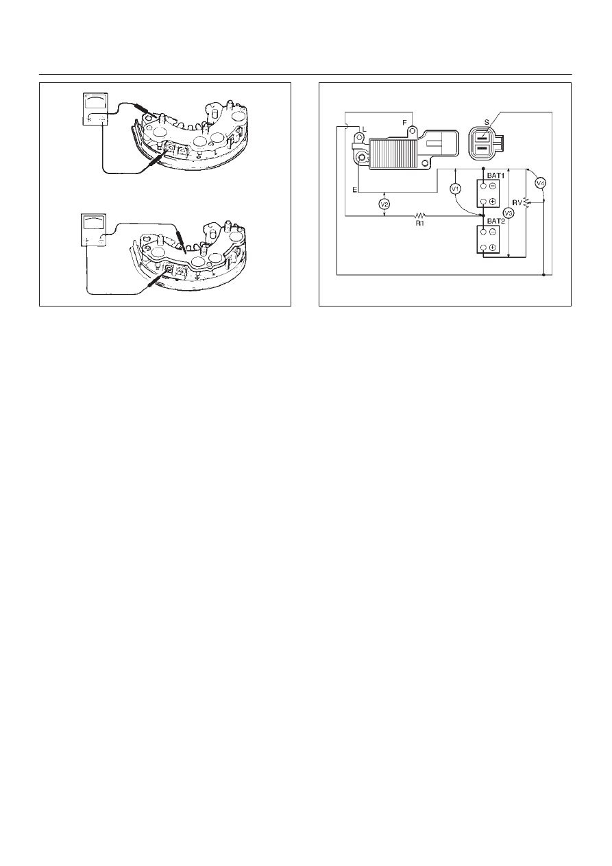
066RS036

IC Regulator Assembly

Connect a variable resistor, two 12V batteries, a fixed
resistor, and a voltmeter to the IC regulator as shown in
illustration.

a. Measuring equipment specifications
1. Fixed resistor (R1) : 10 Ohms /3W
2. Variable resistor (Rv) : 0-300 Ohms/12W
3. Batteries (BAT1, BAT2) : 12V (2 Batteries)
4. DC voltmeter : 0-50V/0.5 steps (4 Check points)
b. Measuring procedure
1. Measure the voltage “V1” across the first battery

(BAT1). If the reading is between 10 and 13 volts,
the battery is normal.

2. Measure the voltage “V3” across both the batteries

(BAT1, BAT2). If the reading is between 20 and 26
bolts, the batteries are normal.

3. Gradually increase the resistance of the variable

resistor from zero.  Measure the voltage “V2” (the
voltage across the F and E terminals).

Check to see that the voltage across “V1” changes at
this time.  If there is no change, the voltage regulator
is faulty and must be replaced.

4. Measure the voltage at “V4” (the voltage across the

variable resistor center tap and terminal E with the
variable resistor resistance held constant).  The
measure voltage should be within the specified
(14.4

±

0.3 volts) limits.  If it is not, the regulator must

be replaced.

066RX003

Reassembly

To reassemble, follow the disassembly steps in the
reverse order, noting the following points:

NOTE:

D

Never make battery connections with polarities
reversed, or battery will be shorted via the diodes.
This will cause damage to the diodes.

D

Do not connect generator B terminal to ground; it is
connected directly to the battery.
This cable will burn if it is connected to ground.

D

Make sure to disconnect the positive (+) terminal of
the battery when quick-charging battery .
Diodes may be damaged due to abnormal pulse
voltage generated bye the quick charger.

D

When reassembling the front section to rear section,
insert a stiff wire into hole in the rear face of the rear
cover from the outboard side to support the brush in
raised position, then insert the front section to which
rotor is assembled.

D

Reassemble parts carefully to be sure they fit into
their original position, paying attention to the
insulated portions.

D

Wipe insulating tubes, washers and plates clean and
install them in position carefully to avoid getting oil or
grease on them.

6D3–25

STARTING AND CHARGING SYSTEM

1. Using a press with a socket wrench attached,

reassemble rotor and rear end cover assembly in the
front cover.

066RS022

2. Install pulley on the rotor.

Secure the pulley directly in the vise between two
copper plates, and tighten nut to the specified torque.

Torque: 111 N·m (82 lb ft)

066RS010

Bench Test

Conduct a bench test of the generator.

066RS023

Preparation

Remove generator from the vehicle (see “Generator
removal”).

1. Secure generator to the bench test equipment and

connect wires.
Terminal “IG” for energization
Terminal “L” for neutral (warning lamp)
Terminal “B” for output

2. Conduct the generator characteristic test.

Characteristics of generator are shown in illustration.
Repair or replace the generator if its outputs are
abnormal.

066RX001

6D3–26 STARTING AND CHARGING SYSTEM

Main Data and Specifications

General Specifications

Battery voltage

V

12

Rated output

A

90

Direction of rotation

(as viewed from pulley side)

Clockwise

Rated rotation speed

rpm

5000

Maximum speed

rpm

18000

6E2–1

6VD1 3.2L ENGINE DRIVEABILITY AND EMISSIONS

FRONTERA

ENGINE

ENGINE DRIVEABILITY AND EMISSIONS

CONTENTS

Specification

6E2–5

. . . . . . . . . . . . . . . . . . . . . . . . . . 

Tightening Specifications

6E2–5

. . . . . . . . . . . . . . . 

Diagrams and Schematics

6E2–6

. . . . . . . . . . . . . . . . 

PCM Wiring Diagram (1 of 8)

6E2–6

. . . . . . . . . . . . 

PCM Wiring Diagram (2 of 8)

6E2–7

. . . . . . . . . . . . 

PCM Wiring Diagram (3 of 8)

6E2–8

. . . . . . . . . . . . 

PCM Wiring Diagram (4 of 8)

6E2–9

. . . . . . . . . . . . 

PCM Wiring Diagram (5 of 8)

6E2–10

. . . . . . . . . . . . 

PCM Wiring Diagram (6 of 8)

6E2–11

. . . . . . . . . . . . 

PCM Wiring Diagram (7 of 8)

6E2–12

. . . . . . . . . . . . 

PCM Wiring Diagram (8 of 8)

6E2–13

. . . . . . . . . . . . 

PCM Pinouts

6E2–14

. . . . . . . . . . . . . . . . . . . . . . . . . . . 

PCM Pinout Table, 32-Way Red Connector
 – Row “A”

6E2–14

. . . . . . . . . . . . . . . . . . . . . . . . . . . . 

PCM Pinout Table, 32-Way Red Connector
 – Row “B”

6E2–15

. . . . . . . . . . . . . . . . . . . . . . . . . . . . 

PCM Pinout Table, 32-Way White Connector
 – Row “C”

6E2–16

. . . . . . . . . . . . . . . . . . . . . . . . . . . . 

PCM Pinout Table, 32-Way White Connector
 – Row “D”

6E2–17

. . . . . . . . . . . . . . . . . . . . . . . . . . . . 

PCM Pinout Table, 32-Way Blue Connector
 – Row “E”

6E2–18

. . . . . . . . . . . . . . . . . . . . . . . . . . . . 

PCM Pinout Table, 32-Way Blue Connector
 – Row “F”

6E2–19

. . . . . . . . . . . . . . . . . . . . . . . . . . . . 

Component Locators

6E2–20

. . . . . . . . . . . . . . . . . . . . 

Engine Component Locator Table

6E2–20

. . . . . . . . 

Undercarriage Component Locator

6E2–21

. . . . . . 

Undercarriage Component Locator Table

6E2–21

Sensors and Miscellaneous Component
 Locators

6E2–22

. . . . . . . . . . . . . . . . . . . . . . . . . . . . . . . 

Fuse and Relay Panel (Underhood Electrical
 Center)

6E2–24

. . . . . . . . . . . . . . . . . . . . . . . . . . . . . . . . 

Diagnosis

6E2–25

. . . . . . . . . . . . . . . . . . . . . . . . . . . . . 

Strategy-Based Diagnostics

6E2–25

. . . . . . . . . . . . . 

Strategy-Based Diagnostics

6E2–25

. . . . . . . . . . . . . 

DTC Stored

6E2–25

. . . . . . . . . . . . . . . . . . . . . . . . . . . 

No DTC

6E2–25

. . . . . . . . . . . . . . . . . . . . . . . . . . . . . . 

No Matching Symptom

6E2–25

. . . . . . . . . . . . . . . . . 

Intermittents

6E2–25

. . . . . . . . . . . . . . . . . . . . . . . . . . 

No Trouble Found

6E2–25

. . . . . . . . . . . . . . . . . . . . . 

Verifying Vehicle Repair

6E2–25

. . . . . . . . . . . . . . . . 

General Service Information

6E2–25

. . . . . . . . . . . . . . 

Non-OEM Parts

6E2–25

. . . . . . . . . . . . . . . . . . . . . . . 

Environment

6E2–26

. . . . . . . . . . . . . . . . . . . . . . . . . . 

Emissions Control Information Label

6E2–26

. . . . . 

Maitenance Schedule

6E2–26

. . . . . . . . . . . . . . . . . . 

Visual/Physical Engine Compartment
 Inspection

6E2–26

. . . . . . . . . . . . . . . . . . . . . . . . . . . . 

Basic Knowledge of Tools Required

6E2–26

. . . . . . 

Seral Data Communications

6E2–26

. . . . . . . . . . . . . . 

Class II Serial Data Communications

6E2–26

. . . . . 

On-Board Diagnostic (OBD)

6E2–26

. . . . . . . . . . . . . . 

On-Board Diagnostic Tests

6E2–26

. . . . . . . . . . . . . 

Comprehensive Component Monitor
 Diagnostic Operation

6E2–27

. . . . . . . . . . . . . . . . . . 

Common OBD Terms

6E2–27

. . . . . . . . . . . . . . . . . . 

The Diagnostic Executive

6E2–28

. . . . . . . . . . . . . . . 

DTC Types

6E2–29

. . . . . . . . . . . . . . . . . . . . . . . . . . . 

Verifying Vehicle Repair

6E2–30

. . . . . . . . . . . . . . . . 

Reading Diagnostic Trouble Codes Using
 the TECH 2 Scan Tool

6E2–30

. . . . . . . . . . . . . . . . . 

Tech 2

6E2–31

. . . . . . . . . . . . . . . . . . . . . . . . . . . . . . . 

Tech 2 Features

6E2–31

. . . . . . . . . . . . . . . . . . . . . . . 

Getting Started

6E2–32

. . . . . . . . . . . . . . . . . . . . . . . . 

Operating Procedure (For Example)

6E2–32

. . . . . 

DTC Modes

6E2–33

. . . . . . . . . . . . . . . . . . . . . . . . . . . 

DTC Information Mode

6E2–34

. . . . . . . . . . . . . . . . . 

Miscellaneous Test

6E2–34

. . . . . . . . . . . . . . . . . . . . 

Lamps Test

6E2–35

. . . . . . . . . . . . . . . . . . . . . . . . . . . 

Relays Test

6E2–35

. . . . . . . . . . . . . . . . . . . . . . . . . . . 

EVAP Test

6E2–37

. . . . . . . . . . . . . . . . . . . . . . . . . . . . 

Idle Air Control System Test

6E2–37

. . . . . . . . . . . . . 

Fuel System Test

6E2–39

. . . . . . . . . . . . . . . . . . . . . . 

EGR Control Test

6E2–40

. . . . . . . . . . . . . . . . . . . . . . 

Variable Intake Manifold Solenoid Test

6E2–41

. . . 

Injector Balance Test

6E2–41

. . . . . . . . . . . . . . . . . . . 

Plotting Snapshot Graph

6E2–42

. . . . . . . . . . . . . . . . . 

Plotting Graph Flow Chart (Plotting graph
 after obtaining vehicle information)

6E2–43

. . . . . . 

Flow Chart for Snapshot Replay
 (Plotting Graph)

6E2–44

. . . . . . . . . . . . . . . . . . . . . . . 

Primary System-Based Diagnostics

6E2–45

. . . . . . . . 

Primary System-Based Diagnostics

6E2–45

. . . . . . 

Fuel Control Heated Oxygen Sensors

6E2–45

. . . . 

HO2S Heater

6E2–45

. . . . . . . . . . . . . . . . . . . . . . . . . 

On-Board Diagnostic (OBD) System Check

6E2–46

Circuit Description

6E2–46

. . . . . . . . . . . . . . . . . . . . . 

Diagnostic Aids

6E2–46

. . . . . . . . . . . . . . . . . . . . . . . . 

A/C Clutch Control Circuit Diagnosis

6E2–48

. . . . . . . 

Circuit Description

6E2–49

. . . . . . . . . . . . . . . . . . . . . 

Diagnostic Aids

6E2–49

. . . . . . . . . . . . . . . . . . . . . . . . 

A/C Clutch Diagnosis

6E2–49

. . . . . . . . . . . . . . . . . . 

Electronic Ignition System Diagnosis

6E2–54

. . . . . . . 

SECTION


Content   ..  296  297  298  299   ..