Opel Frontera UE. Manual - part 270


  Index      Opel     Opel Frontera UE - service repair manual 1999-2001 year


Search            


Content   ..  268  269  270  271   ..


Opel Frontera UE. Manual - part 270


6A–44

ENGINE MECHANICAL (6VD1 3.2L)

D

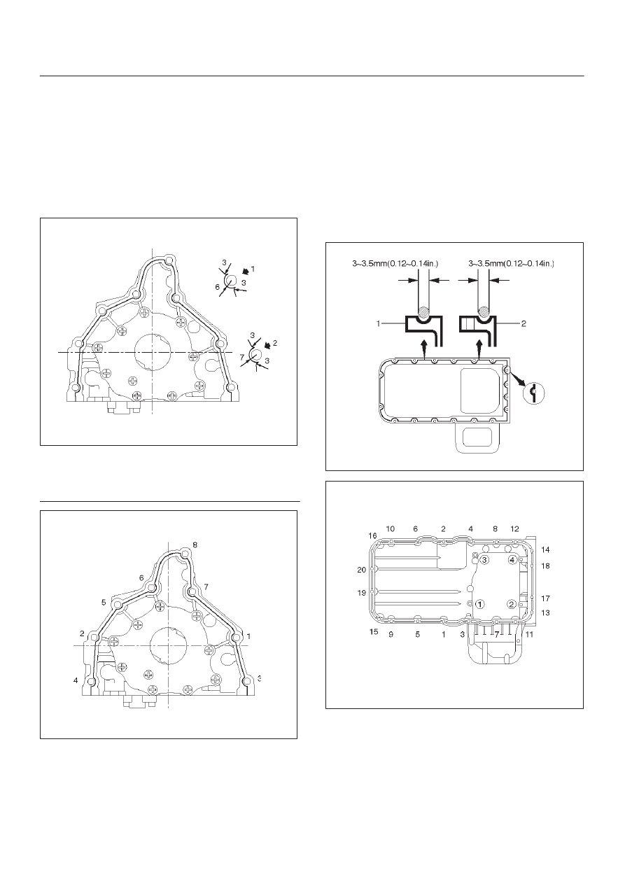
Apply sealant (TB1207B or equivalent) to the oil
pump mounting surface.

D

The oil pump assembly must be installed within 5
minutes after sealant application before the sealant
hardens.

D

Apply engine oil to oil seal lip.

D

Install oil pump in the cylinder block and tighten
fixing bolts to the specified torque.

Torque : 25 N·m (2.5 Kg·m/18 lb ft)

051RW002

Legend

(1) Around Bolt Holes
(2) Around Dowel Pin

051RW001

9. Install oil strainer with O-ring, tighten to the specified

torque.

Torque : 25 N·m (2.5 Kg·m/18 lb ft)

10. Install oil pipe with O-ring, tighten fixing bolts to the

specified torque.

Torque : 25 N·m (2.5 Kg·m/18 lb ft)

11. Install crankcase.

D

Remove oil on crankcase mounting surface and dry
the surface.

D

Properly apply a 4.5 mm (0.7 in) wide bead of
sealant (TB1207C or equivalent) to the crankcase
mounting surface. The bead must be continuous.

D

The crankcase must be installed within 5 minutes
after sealant application before the sealant
hardens.

D

Tighten fixing bolts to the specified torque.

Torque : 10 N·m (1.0 Kg·m/89 lb in)

013RW010

013RW004

12. Install oil pan

D

Remove oil on oil pan mounting surface and dry the
surface.

D

Properly apply a 4.5 mm (0.7 in) wide bead of
sealant (TB1207C or equivalent) to the oil pan
mounting surface. The bead must be continuous.

D

The oil pan must be installed within 5 minutes after
sealant application to prevent premature hardening
of sealant.

6A–45

ENGINE MECHANICAL (6VD1 3.2L)

D

Tighten fixing bolts to the specified torque.

Torque : 25 N·m (2.5 Kg·m/18 lb ft)

013RW003

013RW002

13. Install timing belt.

D

Refer to installation procedure for Timing Belt in this
manual.

14. Install engine assembly.

D

Refer to installation procedure for Engine in this
manual.

6A–46

ENGINE MECHANICAL (6VD1 3.2L)

Rear Oil Seal

Removal

1. Remove transmission assembly.

D

Refer to removal procedure for Transmission
section in this manual.

2. Remove flywheel.
3. Remove rear oil seal using a seal remover.

NOTE: Take care not to damage the crankshaft or oil seal
retainer when removing oil seal.

Installation

1. Apply engine oil to oil seal lip and install oil seal using

5–8840–2286–0.

015RS017

2. Install flywheel.

D

Clean tapped holes in the crankshaft.

D

Remove oil on the crankshaft and flywheel
mounting surface.

D

Tighten fixing bolts to the specified torque.

NOTE: Do not reuse the bolts and do not apply oil or
thread lock to the bolts.

Torque : 54 N·m (5.5 Kg·m/40 lb ft)

015RS018

3. Install transmission.

D

See Transmission section in this manual.

CAUTION: When  assembling the engine and
transmission, confirm that dowels have been
mounted in the specified positions at the engine
side. Take care that dowel positions are different
between the manual transmission and the automatic
transmission.
Otherwise, the transmission may be damaged.

012RS009

6A–47

ENGINE MECHANICAL (6VD1 3.2L)

Engine Assembly

Removal

515RX013

1. Disconnect battery ground and positive cable.
2. Remove battery.
3. Make alignment mark on the engine hood and hinges

before removal in order to return the hood to original
position exactly.

4. Remove engine hood.
5. Drain radiator coolant.
6. Disconnect accelerator cable and automatic cruise

control cable from throttle valve on common
chamber.

7. Disconnect air duct with air cleaner cover.
8. Remove air cleaner assembly.
9. Disconnect canister vacuum hose.

10. Disconnect vacuum booster hose.

11. Disconnect three engine harness connectors.

12. Disconnect harness connector to transmission (left

front side of engine compartment), disconnect shift
on the fly harness connector from front side of front
axle and remove transmission harness bracket from
engine left side.

13. Disconnect ground cable between engine and frame.
14. Disconnect bonding cable connector on the back of

right dash panel.

15. Disconnect bonding cable terminal on the left bank.
16. Disconnect starter harness connector from starter.
17. Disconnect generator harness connector from

generator.

18. Disconnect coolant reserve tank hose from radiator.
19. Remove radiator upper and lower hoses.
20. Remove upper fan shroud.
21. Remove cooling fan assembly four fixing nuts, then

the cooling fan assembly.

22. Move drive belt tensioner to loose side using wrench

then remove drive belt.

23. Remove power steering pump fixing bolts, then

power steering pump. Place the power steering pump
along with piping on the body side.

24. Remove air conditioning compressor fixing bolts from

bracket and place the compressor along with piping
on the body side.

25. Remove O

2

 sensor harness connectors from exhaust

front pipe.

26. Remove three exhaust pipe fixing nuts from each

bank.

27. Remove two exhaust pipe fixing nuts from each

exhaust pipe, then move exhaust pipe to rear side of
vehicle.

28. Remove flywheel dust covers.
29. Disconnect two heater hoses from engine.
30. Disconnect fuel hoses from right side of transmission.

CAUTION: Plug fuel pipes on engine side and fuel
hoses from fuel tank.

31. Remove transmission assembly. Refer to

Transmission section in this manual.

32. Support the engine by engine hoist.
33. Remove two left side engine mount fixing bolts from

engine mount on chassis side.

34. Remove two right side engine mount fixing bolts from

engine mount on chassis side.

35. Remove engine assembly.

Installation

CAUTION: When  assembling the engine and
transmission, confirm that dowels have been
mounted in the specified positions at the engine
side. Take care that dowel positions are different
between the manual transmission and the automatic
transmission.


Content   ..  268  269  270  271   ..