Opel Frontera UE. Manual - part 234
6E1–234
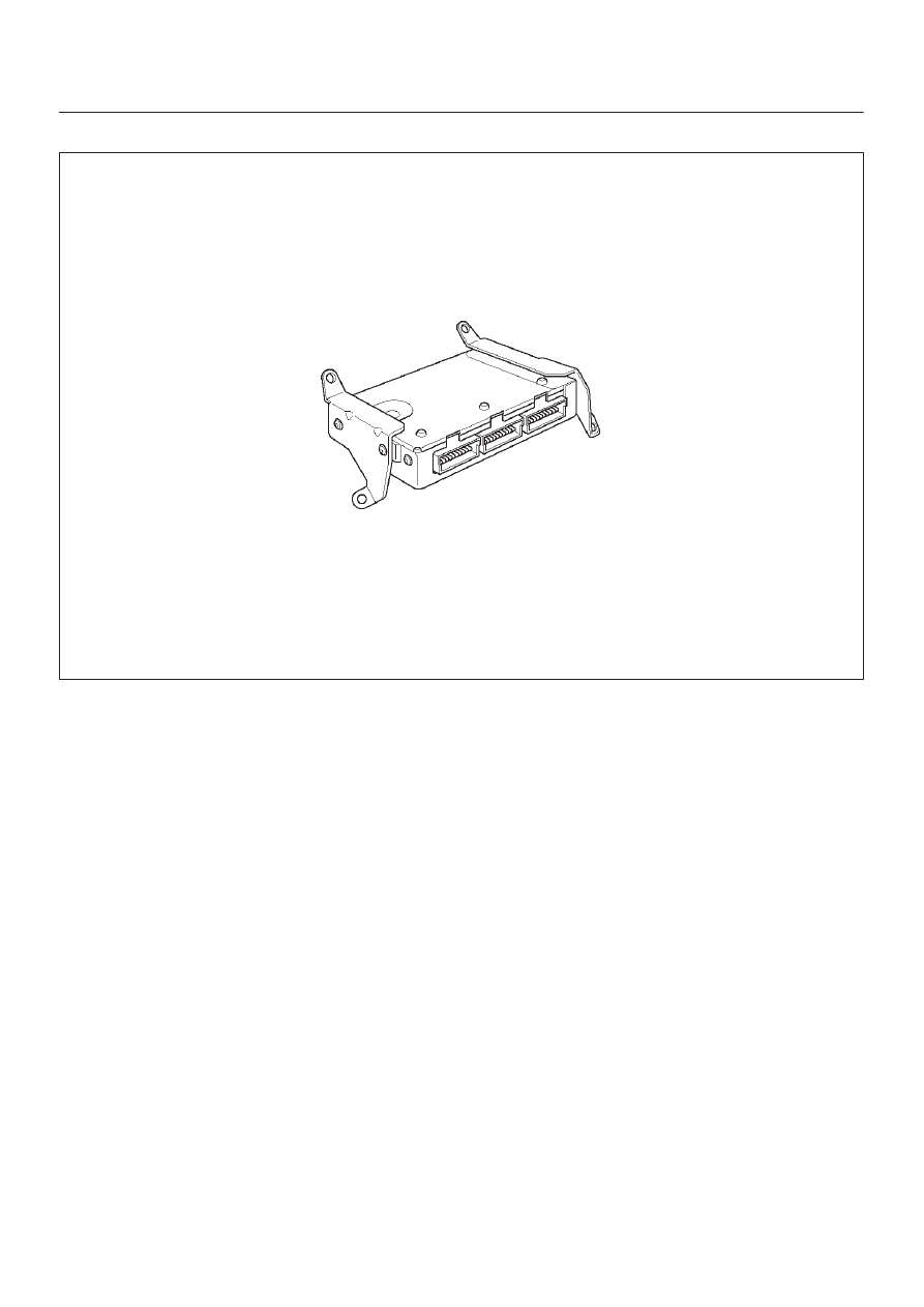
X22SE 2.2L ENGINE DRIVEABILITY AND EMISSION
DIAGNOSTIC TROUBLE CODE (DTC) P1640 ODM OUTPUT CIRCUIT FAULT
014RX002
Circuit Description
Output driver modules (ODMs) are used by the engine
control module(ECM) to turn ON many of the current
driven devices that are needed to control various engine
and transmission functions. Each ODM is capable of
controlling up to 11 separate outputs by applying ground
to the device which the ECM is commanding ON.
ODMs have the capability of diagnosing each output
circuit individually. DTC P1640 set indicates an improper
voltage level has been detected on an ODM output.
If the ECM detects an open circuit condition and a shorted
to voltage circuit condition on the same circuit at the same
time, then DTC P1640 will set. DTC P1640 is a type D
code.
Conditions for Setting the DTC
D
Ignition ON.
D
Above conditions occur for at least 2.5 seconds.
D
The ECM detects an open circuit condition and a
shorted to voltage circuit condition on the same circuit
at the same time.
Action Taken When the DTC Sets
D
The ECM will not illuminate the malfunction indicator
lamp (MIL).
D
The ECM will store conditions which were present
when the DTC was set as Failure Records only. This
information will not be stored as Freeze Frame data.
Conditions for Clearing the DTC
D
A history DTC P1640 will clear after 40 consecutive
warm up cycles occur without a fault.
D
DTC P1640 can be cleared by using the Scan Tool’s
”Clear Info” function.
Diagnostic Aids
Check for the following conditions:
D
Poor connection at ECM – Inspect harness connectors
for backed–out terminals, improper mating, broken
locks, improperly formed or damaged terminals, and
poor terminal to wire connection.
D
Damaged harness Inspect the wiring harness for
damage. If the harness appears to be OK, disconnect
the ECM, turn the ignition ON and observe a voltmeter
connected to the MIL driver circuit at the ECM harness
connector while moving connectors and wiring
harnesses relates to the MIL. A change in voltage will
indicate the location of the fault.
D
Reviewing the Failure Records vehicle mileage since
the diagnostic test last failed may help determine how
often the condition that caused the DTC to be set
occurs. This may assist in diagnosing the condition.
The following ECM pins are controlled by
output driver modules (ODMs):
D
A13 MIL LAMP
D
A14 Rear Defogger
D
B14 A/C Clutch
D
B16 EVAP Canister Parge Solenoid