Opel Frontera UE. Manual - part 230
6E1–218
X22SE 2.2L ENGINE DRIVEABILITY AND EMISSION
DIAGNOSTIC TROUBLE CODE (DTC) P1121 THROTTLE POSITION (TP)
SENSOR CIRCUIT INTERMITTENT HIGH VOLTAGE
D06RX118
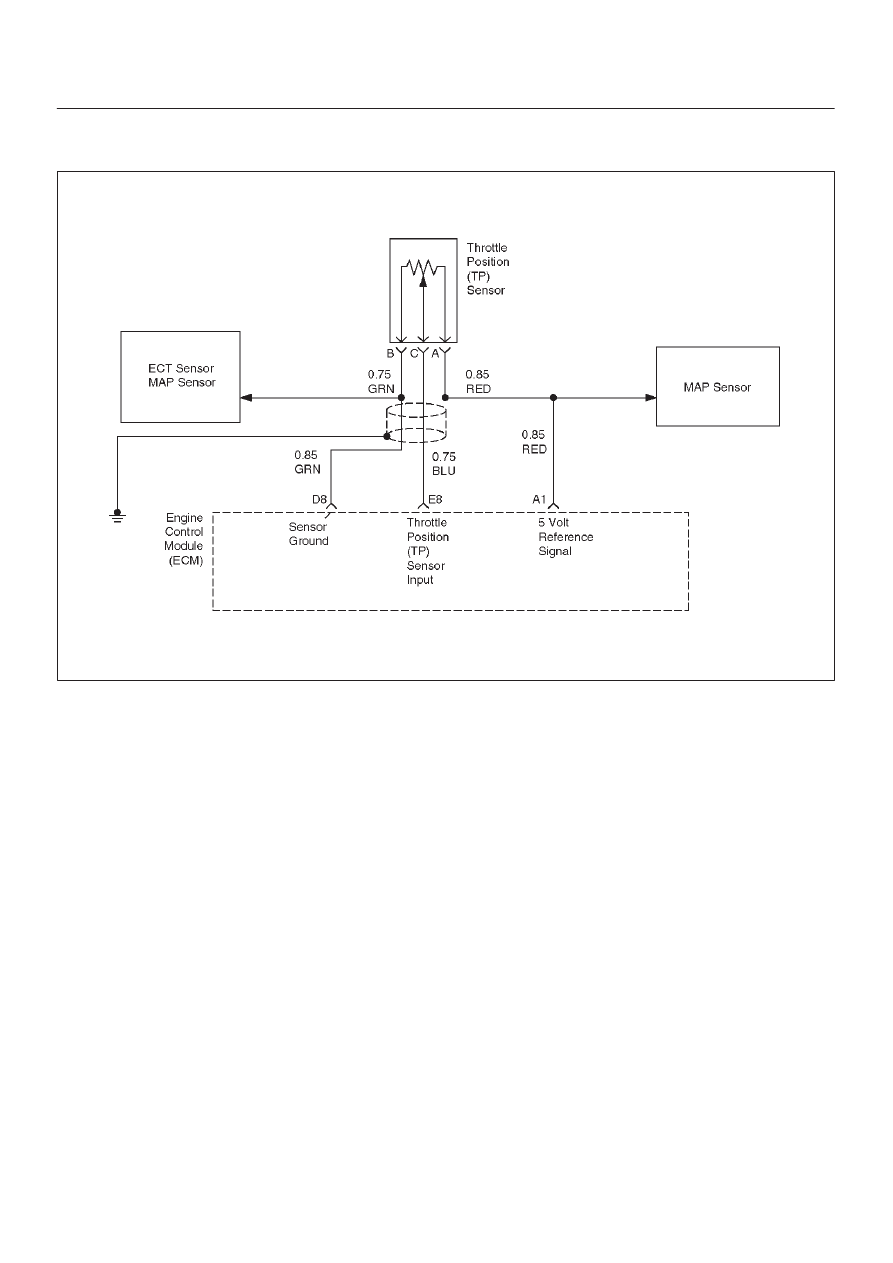
Circuit Description
The throttle position (TP) sensor circuit provides a voltage
signal that changes relative to the throttle blade angle.
The signal voltage will vary from less than 1 volt at closed
throttle to more than 4 volts at wide open throttle (WOT).
The TP signal is used by the engine control module
(ECM) for fuel control and for most of the ECM controlled
outputs. If the ECM detects a TP signal that is
intermittently above the range of the TP sensor,
Diagnostic Trouble Code P1121 will be set. DTC P1121 is
a type D code.
Conditions for Setting the DTC
D
The ignition is ON.
D
TP sensor indicates a throttle position voltage
intermittently greater than 4.88 volts for a total of 0.15
seconds over a 1.5–second period.
Action Taken When the DTC Sets
D
The ECM will not illuminate the malfunction indicator
lamp (MIL).
D
The ECM will store conditions which were present
when the Diagnostic Trouble Code set as Failure
Records data only. This information will not be stored
as Freeze Frame data.
Conditions for Clearing the DTC
D
A history Diagnostic Trouble Code P1121 will clear
after 40 consecutive warm–up cycles have occurred
without a fault.
D
Diagnostic Trouble Code P1121 can be cleared by
using the Scan Tool’s ”Clear Info” function or by
disconnecting the ECM battery feed.
Diagnostic Aids
Check for the following conditions:
D
Poor connection at ECM – Inspect the harness
connectors for backed–out terminals, improper
mating, broken locks, improperly formed or damaged
terminals, and poor terminal–to–wire connection.
D
The TP sensor shares a 5 Volt reference with the MAP
sensor and Fuel Pressure sensor.
If these codes are also set, it could indicate a
problem with the 5 Volt reference circuit or
components itself.
D
The TP sensor share a ground with the MAP and the
Fuel Pressure sensor.
D
Damaged harness – Inspect the wiring harness for
damage; shorts to ground, shorts to battery positive,
and open circuits. If the harness appears to be OK,
observe the throttle position display on the Tech 2 while
moving connectors and wiring harnesses related to the
TP sensor. A change in the display will indicate the
location of the fault.