Opel Frontera UE. Manual - part 195
6E1–78
X22SE 2.2L ENGINE DRIVEABILITY AND EMISSION
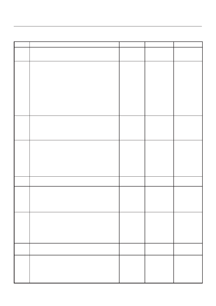
Fuel System Diagnosis
Step
Action
Value(s)
Yes
No
1
Was the ”On–Board Diagnostic (OBD) System Check”
performed?
—
Go to Step 2
Go to OBD
System
Check
2
1. Turn the ignition OFF.
2. Turn the air conditioning system OFF.
3. Relieve fuel system pressure and install the fuel
pressure gauge.
4. Turn the ignition ON.
NOTE: The fuel pump will run for approximately 2
seconds. Use the Tech 2 to command the fuel pump
ON.
5. Observe the fuel pressure indicated by the fuel
pressure gauge with the fuel pump running.
Is the fuel pressure within the specified limits?
283–376 kPa
(41–55 psi)
Go to Step 3
Go to Step 17
3
NOTE: The fuel pressure will drop when the fuel pump
stops running, then it should stabilize and remain
constant.
Does the fuel pressure indicated by the fuel pressure
gauge remain constant?
—
Go to Step 4
Go to Step 12
4
1. When the vehicle is at normal operating
temperature, turn the ignition ON to build fuel
pressure and observe the measurement on the
gauge.
2. Start the engine and observe the fuel pressure
gauge.
Did the reading drop by the amount specified after the
engine was started?
21–105 kPa
(3–15 psi)
Go to Step 5
Go to Step 9
5
Is fuel pressure dropping off during acceleration,
cruise, or hard cornering?
—
Go to Step 6
Check for
improper fuel
6
Visually and physically inspect the following items for a
restriction:
D
The in–pipe fuel filter.
D
The fuel feed line.
Was a restrication found?
—
Verify repair
Go to Step 7
7
Remove the fuel tank and visually and physically
inspect the following items:
D
The fuel pump strainer for a restriction.
D
The fuel line for a leak.
D
Verify that the correct fuel pump is in the vehicle.
Was a problem found in any of these areas?
—
Verify repair
Go to Step 8
8
Replace the fuel pump.
Is the action complete?
—
Verify repair
—
9
1. Disconnect the vacuum hose from the fuel pressure
regulator.
2. With the engine idling, apply 12–14 inches of
vacuum to the fuel pressure regulator.
Does the fuel pressure indicated by the fuel pressure
gauge drop by the amount specified?
21–105 kPa
(3–15 psi)
Go to Step 10
Go to Step 11