Opel Frontera UE. Manual - part 174


  Index      Opel     Opel Frontera UE - service repair manual 1999-2001 year


Search            


Content   ..  172  173  174  175   ..


Opel Frontera UE. Manual - part 174


STARTING AND CHARGING SYSTEM (X22SE 2.2L)

6D3–9

Generator

Removal

1. Disconnect battery ground cable.

2. Move drive belt tensioner to loose side using wrench 

then remove drive belt.

3. Disconnect terminal “B" wiring connector and 

connector.

4. Remove generator bracket (1), (2) and remove 

generator assembly.

065RW025

Inspection

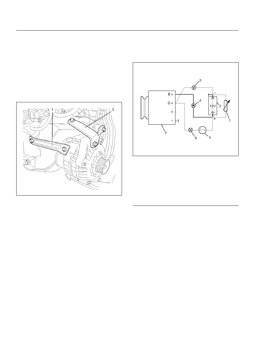
Generator Power and Circuit Diagram

066RW020

Legend

EndOFCallout

1. Disconnect battery.

2. Close off connecting cable from alternator terminal 

“B+".

3. Set ammeter (measuring range 100A) in 

disconnected line.

4. Connect controllable load resistor to battery 

terminal.

5. Set resistor in front of connection to “0"; connect first 

to battery, then to resistor.

6. Connect tachometer.

7. Connect oscilloscope according to manufacturer's 

instructions.

8. Connect battery.

9. Start engine and read off resulting current at various 

engine speeds.

(1) Load resistor, set parallel to battery
(2) Battery
(3) Voltmeter
(4) Ammeter
(5) Ignition Lock
(6) Charge Telltale
(7) Generator

6D3–10

STARTING AND CHARGING SYSTEM (X22SE 2.2L)

Generator Power

1. Adjust load resistor, if the required load currents are 

not attained.

2. The shape of the voltage curves on oscilloscope 

curve should be regular.

3. Test value: 5 to 7A.
4. If the required minimum current intensity is not 

attained, or if the oscilloscope picture shows 
variations, the alternator should be overhauled.

066RW018

Regulated Voltage Circuit Diagram

066RW019

Legend

EndOFCallout

Installation

1. Install generator assembly and bring generator 

assembly to the position to be installed.

2. Install generator bracket (1), (2) and tighten to the 

specified torque.

Torque:

Long bolt: 35 N·m (3.6 kg·m/26 lb ft)

Short bolt: 20 N·m (2.0 kg·m/15 lb ft)

065RW025

3. Connect wiring harness connector.

4. Move drive belt tensioner to loose side using 

wrench, then install drive belt to normal position.

5. Reconnect battery ground cable.

Disassembly

1. Belt pulley nut.

066RW016

(1) Battery
(2) Ignition Lock
(3) Charge Telltale
(4) Resistor, for attainment of load current with the 

battery set in series

(5) Voltmeter
(6) Ammeter
(7) Generator

STARTING AND CHARGING SYSTEM (X22SE 2.2L)

6D3–11

2. Spring ring, washer, belt pulley halves, spacing ring, 

fan pinion, pulley spring.

3. Voltage regulator with brush holder.

066RW014

4. Drive bearing with clawpole armature.

5. Mark housing halves.

6. 4 fastening bolts.

066RW015

7. Clawpole armature from drive bearing.

8. Lay suitable pipe piece (1) underneath.

066RW013

9. Bearing cover of drive bearing.

10. Ball bearing from drive bearing.

066RW017

6D3–12

STARTING AND CHARGING SYSTEM (X22SE 2.2L)

11. Ball bearing from armature shaft.

066RW012

12. Nut from connecting pins “B+" and “D+".

13. Washers and insulating material.

14. Diode plate.

15. Remove together with stator winding from slip ring 

bearing.

066RW008

16. Spray sleeve (if present).

17. Carefully bend off diode plate.

18. Unsolder stator winding from diode plate.

066RW010

Inspection and Repair

Repair or replace necessary parts if extreme wear or 
damage is found during inspection.

Rotor Assembly

1. Check the rotor slip ring surfaces for contamination 

and roughness. If rough, polish with #500–600 
sandpaper.

066RS014


Content   ..  172  173  174  175   ..