Content .. 1623 1624 1625 1626 ..
Opel Frontera UE. Manual - part 1625
MANUAL TRANSMISSION
7B–49
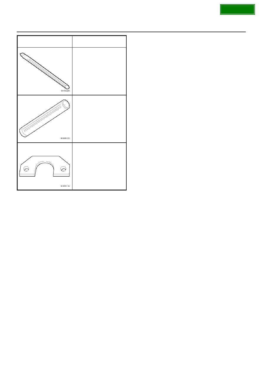
ILLUSTRATION
TOOL NO.
TOOL NAME
5–8840–2293–0
Punch; end nut
5–8840–2194–0
Counter shaft bearing
installer
5–8840–2155–0
Bearing remover
|
|
|
Content .. 1623 1624 1625 1626 ..
MANUAL TRANSMISSION 7B–49 ILLUSTRATION TOOL NO. TOOL NAME 5–8840–2293–0 Punch; end nut 5–8840–2194–0 Counter shaft bearing installer 5–8840–2155–0 Bearing remover |