Opel Frontera UE. Manual - part 1606


  Index      Opel     Opel Frontera UE - service repair manual 1999-2001 year


Search            


Content   ..  1604  1605  1606  1607   ..


Opel Frontera UE. Manual - part 1606


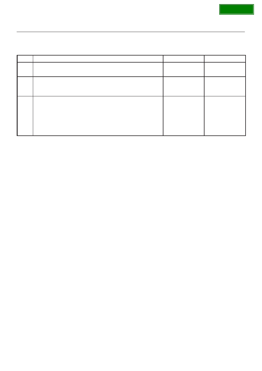
7A1–46 TRANSMISSION CONTROL SYSTEM (4L30–E)

DTC P0722/Flashing Code 78 Transmission Output Speed Sensor (OSS) Low
Input  (Cont’d)

Step

No

Yes

Action

14

Repair the short to B+ in circuit BLU/YEL.

Is the repair complete?

Go to 

Step 16

15

Replace the PCM. Refer to 

Powertrain Control Module (PCM) in

automatic Transmission (4L30–E) section.

Is the replacement complete?

Go to 

Step 16

16

1. After the repair is complete, use the scan tool to select “DTC”,

then “Clear Info” function and operate the vehicle under the
following conditions:

D

Transmission output speed is greater than 101 rpm for 3
seconds.

2. Review the scan tool “DTC Info”.

Has the last test failed or is the current DTC displayed?

Begin diagnosis

again

Go to 

Step 1

Repair verified
Exit DTC table

SECTION

TRANSMISSION CONTROL SYSTEM (4L30–E)

7A1–47

DTC P0723/Flashing Code 79 Transmission Output Speed Sensor (OSS)
Intermittent

D07RY00032

Circuit Description

Output speed information is provided to the PCM by the
OSS, which is a permanent magnet (PM) generator.  The
PM generator produces a pulsing AC voltage.  The AC
voltage level and number of pulses increases as the
speed of the vehicle increases.  The PCM then converts
the pulsing voltage to output speed, which is used for
calculations.  The vehicle speed can be displayed with a
scan tool.
This DTC detects a low output speed when there is a high
engine speed in a drive gear range.  This is a type “C”
DTC.

Conditions For Setting The DTC

Drive range

D

Transmission output speed is greater than 1300 rpm
for 2 seconds.

D

Engine running time is greater than 5 seconds.

D

NORAW–NOLAST < 200 rpm for 2 seconds.

D

NORAW: Latest raw data of output shaft speed.

D

NOLAST: Fitered previous data of output speed.

D

Transmission negative output speed change is
greater than 1300 rpm.

D

Conditions met for 3 seconds.

Action Taken When The DTC Sets

D

Fixed to 4th gear.

D

Maximum line pressure.

D

Inhibit TCC engagement.

D

The PCM will illuminate the CHECK TRANS Lamp.

Conditions For Clearing The DTC/CHECK
TRANS Lamp

D

The PCM will turn off the CHECK TRANS Lamp after
three consecutive ignition cycles without a failure
reported.

D

The DTC can be cleared from the PCM history by
using a scan tool.

D

The DTC will be cleared from history when the vehicle
has achieved 40 warmup cycles without a failure
reported.

D

The PCM will cancel the DTC default actions when
the fault no longer exists and the ignition is cycled “off”
long enough to power down the PCM.

Diagnostic Aids

D

A OSS DTC P0723 will set when output speed has
been detected and is lost.

D

Inspect the wiring for poor electrical connection at the
PCM.  Look for possible bent, backed out, deformed
or damaged terminals.  Check for weak terminal
tension as well.  Also check for a chafed wire that
could short to bare metal or other wiring.  Inspect for a
broken wire inside the insulation.

D

When diagnosing for a possible intermittent short or
open condition, move the wiring harness while
observing test equipment for a change.

Test Description

The numbers below refer to the step numbers on the
diagnostic chart:
3. This test checks the OSS circuit.
4. This test checks the integrity of the OSS.
6. This test checks the 5–volt and ground circuit of the

PCM.

SECTION

7A1–48 TRANSMISSION CONTROL SYSTEM (4L30–E)

DTC P0723/Flashing Code 79 Transmission Output Speed Sensor (OSS)
Intermittent 

Step

Action

Yes

No

1

1. Install the scan tool.
2. With the engine “off”, turn the ignition switch “on”.

NOTE: Before clearing DTC(s), use the scan tool to record “Failure
Records” for reference, as data will be lost when the “Clear Info”
function is used.

3. Record the DTC “Failure Records”.
4. Raise the drive wheels.
5. Start the engine.
6. Place the transmission in any drive range.

With the drive wheels rotating, does the “Trans Output Speed”
increase with the drive wheel speed?

Go to 

Diagnostic
Aids

Go to 

Step 2

2

Check for the most current and/or incorrect calibration.

Is the calibration current?

Go to 

Step 15

Go to 

Step 3

3

1. Turn the ignition “off”.
2. Disconnect the E–22 (J2, RED) PCM connector.
3. Using the J39200 DVOM, measure the resistance between

harness connector terminals E22–22 and E22–55.

Is the reading 3,000 ohms?

Go to 

Step 4

Go to 

Step 5

4

1. Select AC volts.
2. Rotate the rear wheels, ensuring the driveshaft is turning.

Is the voltage greater than 0.5 volts?

Go to 

Step 6

Go to 

Step 7

5

Inspect circuits BLU/YEL and BLU/GRN for a poor connection or
an open circuit.

Was a problem found?

Go to 

Step 16

Go to 

Step 7

6

1. Reconnect the E–22 (J2, RED) PCM connector.
2. Disconnect the OSS harness from the OSS.
3. With the engine “off”, turn the ignition “on”.
4. Using the J 39200 DVOM, measure the voltage at the OSS

harness connector terminals E55–1 and E55–2.

Is the reading between 4.0 to 5.1 volts?

Go to 

Step 15

Go to 

Step 9

7

1. Remove the OSS.
2. Check the output shaft speed sensor rotor for damage or

misalignment. Refer to 

Speed Sensor (Extension Housing) in

Automatic Transmission (4L30–E) section.

Was a problem found?

Go to 

Step 16

Go to 

Step 8

8

Replace the OSS.

Is the replacement complete?

Go to 

Step 16

9

Was the reading in step 6 less than 4.0 volts?

Go to 

Step 11

Go to 

Step 10

10

Was the reading in Step 6 greater than 5.1 volts?

Go to 

Step 14

11

Using the J 39200 DVOM to chassis ground, measure the voltage
on circuit BLU/YEL.

Is the reading between 4.0 to 5.1 volts?

Go to 

Step 12

Go to 

Step 13

12

Repair the open in circuit BLU/GRN.

Is the repair complete?

Go to 

Step 16

13

Check circuit BLU/YEL for a short to ground or open.

Was a problem found and corrected?

Go to 

Step 16

Go to 

Step 15

SECTION

TRANSMISSION CONTROL SYSTEM (4L30–E)

7A1–49

DTC P0723/Flashing Code 79 Transmission Output Speed Sensor (OSS)
Intermittent  (Cont’d)

Step

No

Yes

Action

14

Repair the short to B+ in circuit BLU/YEL.

Is the repair complete?

Go to 

Step 16

15

Replace the PCM. Refer to 

Powertrain Control Module (PCM) in

Automatic Transmission (4L30–E) section.

Is the replacement complete?

Go to 

Step 16

16

1. After the repair is complete, use the scan tool to select “DTC”,

then “Clear Info” function and operate the vehicle under the
following conditions:

D

Transmission output speed is greater than 101 rpm for 3
seconds.

2. Review the scan tool “DTC Info”.

Has the last test failed or is the current DTC displayed?

Begin diagnosis

again

Go to 

Step 1

Repair verified
Exit DTC table

SECTION


Content   ..  1604  1605  1606  1607   ..