Content .. 1584 1585 1586 1587 ..
Opel Frontera UE. Manual - part 1586
7A–66
AUTOMATIC TRANSMISSION (4L30–E)
242RW004
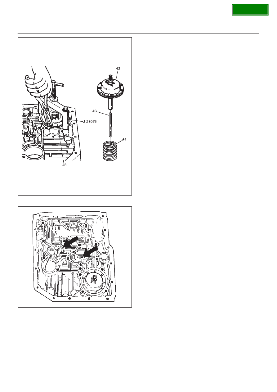
46. Install two check balls (44).
244RW002
47. Inspect main case electrical connector and seal,
replace if necessary.
D
Install electrical 7 way connector/main case and
wiring harness.
48. Install two J–25025–B guide pins into main case.
D
Install main case valve body complete assembly
(45) and manual valve link.
NOTE: Valve must be extended as the short end of
manual valve link is connected to the range selector lever.
Long end of link goes into valve.
D
Install seven 13 mm screws, tighten the specified
torque.
Torque: 20 N
•
m (15 lb ft)
D
Remove two guide pins.
49. Install servo cover gasket, cover (46) and four 13 mm
screws.
Torque: 25 N
•
m (18 lb ft)
50. Connect wiring harness (47) to band control, shift
solenoids, and main case 7 way connector.
51. Install manual detent roller and spring assembly (48)
with clip.
D
Install two 13 mm screws.
Torque: 20 N
•
m (15 lb ft)
52. Install oil filter (49) and three 13 mm screws.
Torque: 20 N
•
m (15 lb ft)
53. Install oil pan gasket, magnet, main oil pan (50),
sixteen 10 mm screws.
Torque: 11 N
•
m (96 lb in)
54. Inspect adapter case electrical connector and seal.
Replace if necessary.
D
Install electrical 4 way connector and harness
assembly (52) in bottom of adapter case.
55. Install gasket, transfer plate, and gasket.
D
Install adapter case valve body (51) complete and
seven 13 mm screws.
Torque: 20 N
•
m (15 lb ft)
56. Connect wiring harness harness assembly (52) to
converter clutch solenoid, force motor, and 4 way
connector.
57. Install oil pan gasket, adapter case oil pan (53), and
twelve 10 mm screws.
Torque: 11 N
•
m (96 lb in)
D
Rotate transmission, with bottom pan facing down.
58. Install mode switch (54), two 10 mm screws, selector
lever nut, and cover.
10 mm screw
Torque: 13 N
•
m (113 lb in)
Nut
Torque: 23 N
•
m (17 lb ft)
D
Adjust using setting tool, refer to
Mode Switch in
this section.
59. Install O-ring (55) on turbine shaft.