Content .. 1566 1567 1568 1569 ..
Opel Frontera UE. Manual - part 1568
6G–13
ENGINE LUBRICATION (6VD1 3.2L)
Oil Filter
Removal
1. Disconnect battery ground cable.
2. Drain engine oil.
3. Remove oil filter using 5–8840–0203–0 filter wrench.
Installation
1. Clean filter fitting surface and apply small amount of
engine oil to sealing surface.
2. Install oil filter cartridge by hand until it comes in
contact with sealing surface then rotate additional 7/8
turn to tighten using 5–8840–0203–0 filter wrench.
050RW001
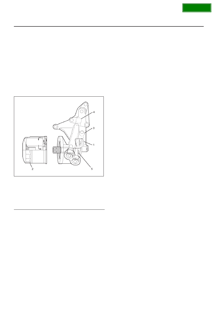
Legend
(1) Oil Pump
(2) Oil Filter
(3) Oil Gallery
(4) From Filter
(5) To Filter
3. Fill engine oil until full level on dipstick.
4. Reconnect battery ground cable.