Opel Frontera UE. Manual - part 1535


  Index      Opel     Opel Frontera UE - service repair manual 1999-2001 year


Search            


Content   ..  1533  1534  1535  1536   ..


Opel Frontera UE. Manual - part 1535


6E–355

6VD1 3.2L ENGINE DRIVEABILITY AND EMISSIONS

Diagnostic Trouble Code (DTC) 

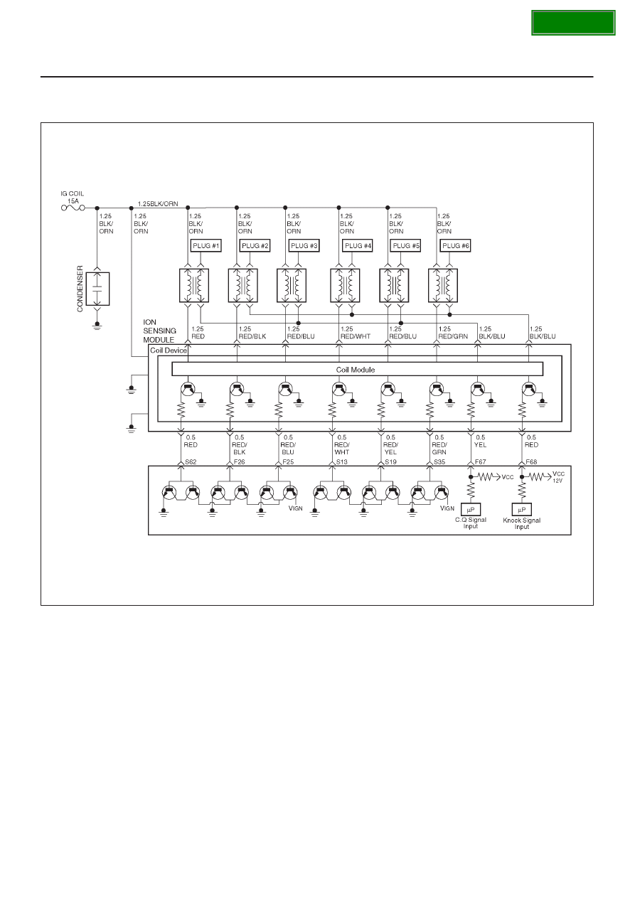
P1326  ION Sensing Module Combustion Quality Input Circuit Fault

060R100135

Circuit Description

The Power Control Module (PCM) checks the validity of
the signals used in the ION Sensing module at the
following engine operating conditions.

D

The test is performed to evacuate the Combustion
Quality (CQ) signal pulse width if it is within a
predetermined range. If the CQ signal pulse width is
out of the predetermined range, the fail counter will be
incremented. If the failure counter exceeds the
calibration, then test is complete and a failure will be
reported. If the sample counter threshold is reached
before the failure threshold, then the test is complete
and a pass will be reported. This test will detect an
open/short in the CQ line circuit, ION Sensing module
faults and analog input faults in the PCM.

Conditions for setting the DTC

D

Ignition voltage is between 10volt and 16 volts.

D

No Crank DTCs set.

D

No cylinder ID DTCs set.

D

CQ pulse width is less than 30

m

s or more than 1070

m

s.

Action Taken When the DTC Sets

D

The PCM will illuminate the malfunction indicator lamp
(MIL) the first time the fault is detected.

D

The PCM calculates an air flow value based on idle air
control valve position, throttle position, RPM and
barometric pressure.

D

The PCM will store conditions which were present
when the DTC was set as Freeze Frame and in the
Failure Records data.

Conditions for Clearing the MIL/DTC

D

The PCM will turn the MIL “OFF” on the third
consecutive trip cycle during which the diagnostic has
been run and the fault condition is no longer present.

SECTION

6E–356

6VD1 3.2L ENGINE DRIVEABILITY AND EMISSIONS

D

A history DTC P1326 will clear after 40 consecutive trip
cycle during which the warm up cycles have occurred
without a fault.

D

DTC P1326 can be cleared using the Tech 2 “Clear
Info” function.

Diagnostic Aids

An intermittent may be caused by the following:

D

Poor connections.

D

Misrouted harness.

D

Rubbed through wire insulation.

D

Broken wire inside the insulation.

Check for the following conditions:

D

Poor connection at PCM-Inspect harness connectors
for backed out terminals, improper mating, broken

locks, improperly formed or damaged terminals, and
poor terminal to wire connection.

D

Damaged harness-Inspect the wiring harness for
damage. If the harness appears to be OK, observe the
moving connectors and wiring harnesses related to the
sensor.
A change in the display will indicate the location of
the fault. If DTC P1326 cannot be duplicated, the
information included in the Failure Records data can
be useful in determined vehicle mileage since the
DTC was last set.

If it is determining that the DTC occurs intermittently,
performing the DTC P1326 Diagnostic Chart may
isolate the cause of the fault.

DTC P1326 - ION Sensing Module Combustion


Step

Action

Value(s)

Yes

No

1

Was the “On-Board (OBD) System Check” performed?

Go to

 Step 2

Go to

 OBD

System

Check

2

1. Ignition “ON”, engine “OFF”.
2. Review and record Tech 2 Failure Records data.
3. Operate the vehicle within Failure Records

conditions as noted.

4.  Using a Tech 2, monitor “DTC”info for DTC P1326.

Does the Tech 2 indicate DTC P1326 failed this
ignition?

Go to

 Step 3

Refer to

Diagnostic

Aids

3

1. Ignition “OFF”.
2. Disconnect the ION Sensing module.
3. Disconnect the PCM.

Is the action complete?

Go to

 Step 4

Go to

 Step 3

4

Check the ION Sensing module harness between the
PCM and ION Sensing module circuit at the QC line
harness connector.

Was a problem found?

Verify repair

Go to

 Step 6

5

1. Disconnect the ignition coil.

Is the action complete?

Go to

 Step 6

Go to

 Step 5

6

Check the ION Sensing module harness between the
ignition coil and ICSS module circuit at the ION Sensing
Module harness connector.

Was a problem found?

Verify repair

Go to

 Step 7

7

Check the following items;

1. Ignition coil and ignition coil circuit.
2. Ignition coil ground circuit for a poor connection.
3. If a problem is found, repair wiring harness as

necessary.

Was a problem found?

Verify repair

Go to

 Step 8 

8

Replace the Ignition coil.

Is the action complete?

Verify repair

Go to

 Step 9 

SECTION

6E–357

6VD1 3.2L ENGINE DRIVEABILITY AND EMISSIONS

DTC P1326 - ION Sensing Module Combustion

  (Cont'd)

Step

No

Yes

Value(s)

Action

9

Check the following items;

1. ION Sensing module ground circuit for a poor

connection.

2. If a problem is found, repair wiring harness as

necessary.

Was a problem found?

Go to

 Step 10

Go to

 Step 11

10

Replace the ION Sensing module.

Is the action complete?

Verify repair

Go to

 Step 10

11

Replace the PCM.

IMPORTANT: The replacement PCM must be
programmed.

Refer to

 ON-Vehicle Service in Power Control Module

and Sensors for procedures.

And also refer to latest Service Bulletin .Check to see
if the latest software is released or not.

And then Down Load the LATEST PROGRAMMED
SOFTWARE to the replacement PCM.

Is the action complete?

Verify repair

SECTION

6E–358

6VD1 3.2L ENGINE DRIVEABILITY AND EMISSIONS

Diagnostic Trouble Code (DTC) 

P1340  ION Sensing Module Cylinder ID Fault (Cylinder Synchronization Fail)

060R100135

Circuit Description

The Power Control Module (PCM) checks the validity of
the signals used in the ION Sensing module at the
following engine operating conditions.

D

This test will return a fault if the cylinder
synchronization routine has not been completed after
a predetermined number of events after crank. This
test will detect fault that will prevent the PCM from
synchronization, such as Knock Signal (KI) -
Combustion Quality (CQ) lines being swapped,
shorted spark plugs, ION Sensing module faults, an
PCM hardware faults. 

Conditions for setting the DTC

D

Ignition voltage is between 11volts and 16 volts.

D

Engine speed  is between 650rpm and 6250rpm.

D

No ECT DTCs set.

D

No injector DTCs set.

D

No Fuel Trim DTCs set.

D

No Misfire DTCs set.

D

No system voltage DTCs set.

Action Taken When the DTC Sets

D

The PCM will ON the MIL after second trip with
detected the fault.

D

The PCM calculates an air flow value based on idle air
control valve position, throttle position, RPM and
barometric pressure.

D

The PCM will store conditions which were present
when the DTC was set as Freeze Frame and in the
Failure Records data.

Conditions for Clearing the MIL/DTC

D

The PCM will turn the MIL “OFF” on the third
consecutive trip cycle during which the diagnostic has
been run and the fault condition is no longer present.

D

A history DTC P1340 will clear after 40 consecutive trip
cycle during which the warm up cycles have occurred
without a fault.

D

DTC P1340 can be cleared using the Tech 2 “Clear
Info” function.

Diagnostic Aids

An intermittent may be caused by the following:

D

Poor connections.

D

Misrouted harness.

D

Rubbed through wire insulation.

D

Broken wire inside the insulation.

Check for the following conditions:

D

Poor connection at PCM-Inspect harness connectors
for backed out terminals, improper mating, broken
locks, improperly formed or damaged terminals, and
poor terminal to wire connection.

SECTION


Content   ..  1533  1534  1535  1536   ..