Content .. 1528 1529 1530 1531 ..
Opel Frontera UE. Manual - part 1530
6E–335
6VD1 3.2L ENGINE DRIVEABILITY AND EMISSIONS
Diagnostic Trouble Code (DTC) P1290 ETC Forced Idle Mode
060R100140
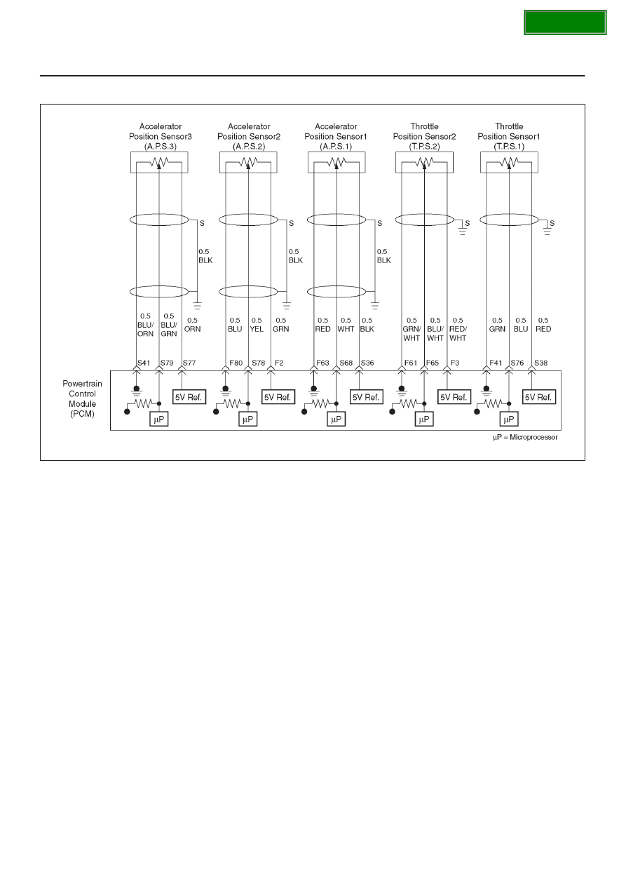
Circuit Description
D
The accelerator position (AP) sensor circuit provides a
voltage signal relative to accelerator pedal angle.
This code detects that if the system is in Forced Idle
Mode. (Fail safe Mode)
DTC P1290 is recorded by the PCM when all AP
sensors are failed.
Conditions for setting the DTC
D
The Ignition is “ON”.
D
Forced Idle Mode is active. (Fail safe Mode)
Action Taken When the DTC Sets
D
The PCM will illuminate the malfunction indicator lamp
(MIL) and reduced powered lamp (RPL) the first time
the fault is detected.
D
The PCM will store conditions which were present
when the DTC was set as Freeze Frame and in the
Failure Records data.
Conditions for Clearing the MIL/DTC
D
The PCM will turn the MIL “OFF” on the third
consecutive trip cycle during which the diagnostic has
been run and the fault condition is no longer present.
D
A history DTC P1290 will clear after 40 consecutive trip
cycle during which the warm up cycles have occurred
without a fault.
D
DTC P1290 can be cleared using the Tech 2 “Clear
Info” function or by disconnecting the PCM battery
feed.
Diagnostic Aids
An intermittent may be caused by the following:
D
Poor connections.
D
Misrouted harness.
D
Rubbed through wire insulation.
D
Broken wire inside the insulation.
Check for the following conditions:
D
Poor connection at PCM-Inspect harness connectors
for backed out terminals, improper mating, broken
locks, improperly formed or damaged terminals, and
poor terminal to wire connection.
D
Damaged harness-Inspect the wiring harness for
damage. If the harness appears to be OK, observe the
AP sensor 1, AP sensor 2, AP sensor 3 display on the
Tech 2 while moving connectors and wiring harnesses
related to the sensor.
A change in the display will indicate the location of
the fault. If DTC P1290 cannot be duplicated, the
information included in the Failure Records data can
be useful in determined vehicle mileage since the
DTC was last set.
If it is determining that the DTC occurs intermittently,
performing the DTC
P1290 Diagnostic Chart may isolate the cause of the
fault.