Content .. 1513 1514 1515 1516 ..
Opel Frontera UE. Manual - part 1515
6E–275
6VD1 3.2L ENGINE DRIVEABILITY AND EMISSIONS
Diagnostic Trouble Code (DTC)
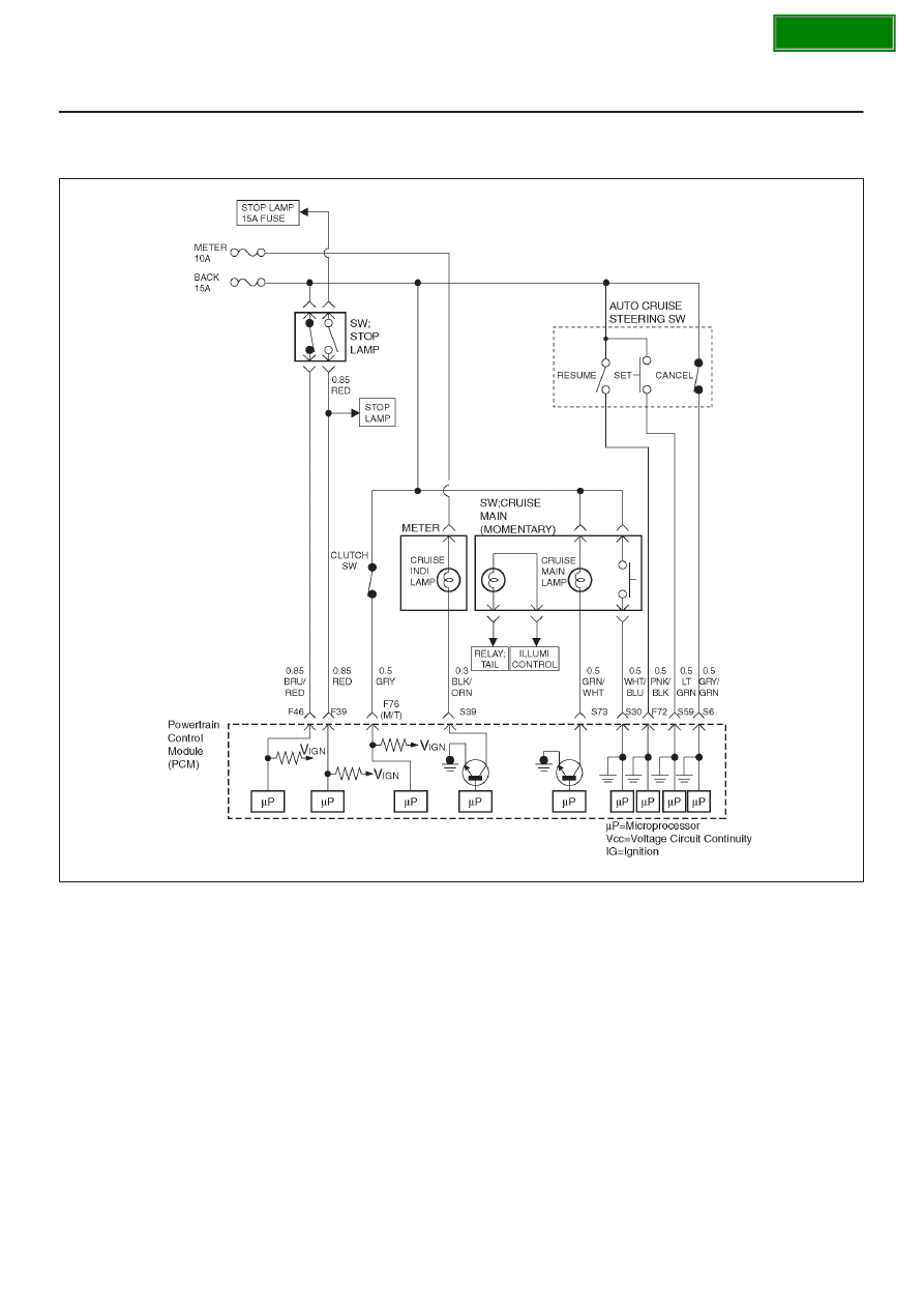
P0567 Cruise Resume Switch Circuit Error
060R100137
Circuit Description
The cruise control keeps the vehicle running at a fixed
speed until a signal canceling this fixed speed is received.
When the main switch is turned on with the vehicle in the
running mode, the battery voltage is applied to powertrain
control module(PCM). When a signal from the control
switch is input to PCM while the vehicle is in this state, the
cruise control system is activated. Also, while the PCM is
operating, the “CRUISE MAIN” indicator light in the meter
assembly lights up.
When the resume switch is “ON”, vehicle speed is
reseated to the previous set speed.
Conditions for setting the DTC
D
The Ignition is “ON”.
D
Engine is running.
D
System voltage is between 11.5 volts and 16 volts.
D
The switch contact remain on for 50 seconds or more.
D
Noises are generated by poor switch contact 100 times
within 1.6 seconds.
Action Taken When the DTC Sets
D
The PCM will not illuminate the malfunction indicator
lamp (MIL).
D
The PCM will store conditions which were present
when the DTC was set in the Failure Records data only.
Conditions for Clearing the MIL/DTC
D
The PCM will turn the MIL “OFF” on the third
consecutive trip cycle during which the diagnostic has
been run and the fault condition is no longer present.
D
A history DTC P0567 will clear after 40 consecutive trip
cycle during which the warm up cycles have occurred
without a fault.