Content .. 1452 1453 1454 1455 ..
Opel Frontera UE. Manual - part 1454
6E–31
6VD1 3.2L ENGINE DRIVEABILITY AND EMISSIONS
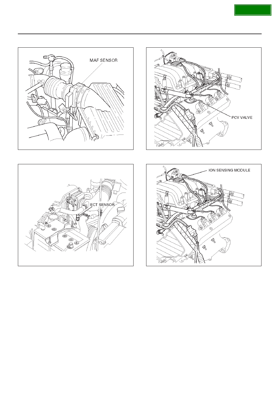
MAF Sensor
T321078
ECT Sensor
060RY00014
PCV Valve
060RY00016
ION Sensing Module
060RY00023
|
|
|
Content .. 1452 1453 1454 1455 ..
6E–31 6VD1 3.2L ENGINE DRIVEABILITY AND EMISSIONS MAF Sensor T321078 ECT Sensor 060RY00014 PCV Valve 060RY00016 ION Sensing Module 060RY00023 |