Opel Frontera UE. Manual - part 1414


  Index      Opel     Opel Frontera UE - service repair manual 1999-2001 year


Search            


Content   ..  1412  1413  1414  1415   ..


Opel Frontera UE. Manual - part 1414


6A–33

ENGINE MECHANICAL (6VD1 3.2L)

Installation

014R100015

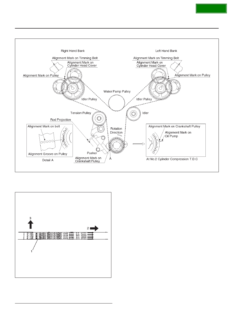
NOTE: For correct belt installation, the letter on the belt
must be able to be read as viewed from the front of the
vehicle.

014RW006

Legend

(1) Timing Belt
(2) Engine Rotation Direction
(3) Cylinder Head Side

SECTION

6A–34

ENGINE MECHANICAL (6VD1 3.2L)

1. Install timing belt.

a. Align the mark (notch) of crankshaft timing pulley

(2) with mark on oil pump (1).
Align the mark (groove) on the crankshaft timing
pulley (3) with alignment mark (white dots line) on
the timing belt (4).

NOTE: When timing marks are aligned, No.2 piston will
be on Top Dead Center.

014RW003

Legend

(1) Alignment Mark on Oil Pump
(2) Groove on Crankshaft Timing Pulley
(3) Alignment Mark on Crankshaft Timing Pulley
(4) Alignment Mark on Timing Belt

b. Align the alignment mark on the RH bank camshaft

drive gear pulley (2) to the alignment mark of the
cylinder head cover RH (3).
The camshaft pulley is not 1:1 with the camshafts.
It is necessary the rotate the camshaft pulley until
the camshaft lobes are in the position as shown in
the diagram on page 6A–34.
The camshaft pulley alignment mark should also
align with alignment mark on the cylinder head
cover.
It may require up to four revolutions of the
camshaft pulley to achieve alignment of all marks.

c. Align the alignment mark (white line) on the timing

belt (1) with alignment mark on the RH bank
camshaft drive gear pulley (2) (on the left side as
viewed from the front of the vehicle) and put the
timing belt on the camshaft drive gear pulley.
Secure the belt with a double clip or equivalent clip.

014RW00004

Legend

(1) Alignment Mark on Timing Belt (White line).
(2) Alignment Mark on Camshaft Drive Gear

Pulley.

(3) Alignemnt Mark on Cylinder Head Cover RH.

d. Align the alignment mark on the LH bank camshaft

drive gear pulley (2) to the alignment mark of the
cylinder head cover LH (3).
The camshaft pulley is not 1:1 with the camshafts.
It is necessary the rotate the camshaft pulley until
the camshaft lobes are in the position as shown in
the diagram on page 6A–34.
The camshaft pulley alignment mark should also
align with alignment mark on the cylinder head
cover.
It may require up to four revolutions of the
camshaft pulley to achieve alignment of all marks.

e. Align the alignment mark (white line) on the timing

belt (1) with the alignment mark on the LH bank
camshaft drive gear pulley (2).
When aligning the timing marks, use a wrench to
turn the camshaft drive gear pulley, then set the
timing mark between timing belt and camshaft
drive gear pulley and put the timing belt on the
camshaft drive gear pulley.
Secure the belt with a double clip or equivalent clip.

SECTION

6A–35

ENGINE MECHANICAL (6VD1 3.2L)

NOTE: It is recommended for easy installation that the
belt be secured with a double clip or equivalent clip after
it is installed the timing belt to each pulley.

014RW00005

Legend

(1) Alignment Mark on Timing Belt (White line).
(2) Alignment Mark on Camshaft Drive Gear

Pulley.

(3) Alignemnt Mark on Cylinder Head Cover LH.

f. Install crankshaft pulley temporarily and tighten

center bolt by hand (do not use a wrench).
Turn the crankshaft pulley clockwise to give some
belt slack between the crankshaft timing pulley and
the RH bank camshaft drive gear pulley.

2. Install pusher and tighten bolt to the specified torque.

Torque : 25 N·m (2.5 kg·m/18 lb ft)

a. Install the pusher while pushing the tension pulley

to the belt.

b. Pull out pin from the pusher.

NOTE: When reusing the pusher, compress the pusher
rod with approximately 980 N (220 lb/100 kg), and insert
a pin (1.4 mm piano wire).

014R100020

Legend

(1) Up Side
(2) Down Side
(3) Direction for Installation
(4) Locking Pin
(5) Apply a force of 980 N (220 lb) when

compressing the pusher rod.

After release the push rod from the locking pin, the
rod projection is approximate 5 mm.

014R100032

Legend

(1) Tensioner Pulley
(2) Crankshaft Pulley Rotation Direction
(3) Crankshaft Pulley
(4) Pusher Assembly

c. Remove double clips or equivalent clips, from

timing belt pulleys.
Turn the crankshaft pulley by six turns and check
for timing mark alignment.

SECTION

6A–36

ENGINE MECHANICAL (6VD1 3.2L)

3.  Install timing belt cover.

Remove crankshaft pulley that was installed in step
1 item 5.
Tighten bolts to the specified torque.

Torque: 19 N·m (1.9 kg·m/14 lb ft)

020RW004

Legend

(1) Timing Belt Cover RH
(2) Timing Belt Cover LH
(3) Timing Belt Cover Lower

020RW003

Legend

(1) Timing Belt Cover
(2) Rubber Bushing
(3) Sealing Rubber
(4) Cylinder Body

4. Install crankshaft pulley using 5–8840–0133–0, hold

the crankshaft pulley and tighten center bolt to the
specified torque.

Torque : 167 N·m (17.0 kg·m/123 lb ft)

5. Install fan pulley bracket and tighten fixing bolts to the

specified torque.

Torque : 22 N·m (2.2 kg·m/16 lb ft)

6. Install power steering pump assembly and tighten to

the specified torque.

Torque : 
M8 bolt : 22 N·m (2.2 kg·m/16 lb ft)
M10 bolt : 46 N·m (4.7 kg·m/34 lb ft)

7. Install cooling fan assembly and tighten bolts/nuts to

the specified torque.

Torque : 22 N·m (2.2 kg·m/16 lb ft) for fan pulley
and fan bracket.

Torque : 10 N·m (1.0 kg·m/87 lb in) for fan and
clutch assembly.

8. Move drive belt tensioner to loose side using wrench,

then install drive belt to normal position.

850RW001

Legend

(1) Crankshaft Pulley
(2) Cooling Fan Pulley
(3) Auto Tensioner
(4) Generator
(5) Air Conditioner Compressor
(6) Power Steering Oil Pump
(7) Idle Pulley
(8) Drive Belt

9. Install radiator upper fan shroud.

10. Install air cleaner assembly.

SECTION


Content   ..  1412  1413  1414  1415   ..