Content .. 1388 1389 1390 1391 ..
Opel Frontera UE. Manual - part 1390
ANTI-LOCK BRAKE SYSTEM
5B–3
4. Remove harness connector.
5. Remove EHCU ASM.
6. Remove EHCU.
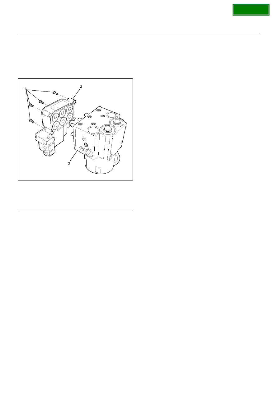
Disassembled View
350RW025
Legend
EndOFCallout
Disassembly
1. Remove fixing bolts from EHCU.
2. Remove coil integrated module from hydraulic unit.
Reassembly
To reassembly, follow the disassembly steps in the
reverse order, noting the following points:
Torque:
Fixing bolts: 4.4 N·m (4.5 kg·cm/39 lb in)
Installation
To install, follow the removal steps in the reverse order,
noting the following points:
Torque:
Hydraulic unit fixing nuts : 22 N·m (2.2 kg·m/16
lbft)
Ground cable : 14 N·m (1.4 kg·m/10 lbft)
Brake pipe (joint bolts) : 16 N·m (1.6 kg·m/12 lbft)
• After installing the hydraulic unit, bleed brakes
completely. See
Hydraulic Brakes
in Power–assisted
brake system section.
(1) Fixing Bolts
(2) Coil Integrated Module
(3) Hydraulic Unit (H/U)