Content .. 1354 1355 1356 1357 ..
Opel Frontera UE. Manual - part 1356
4C–46
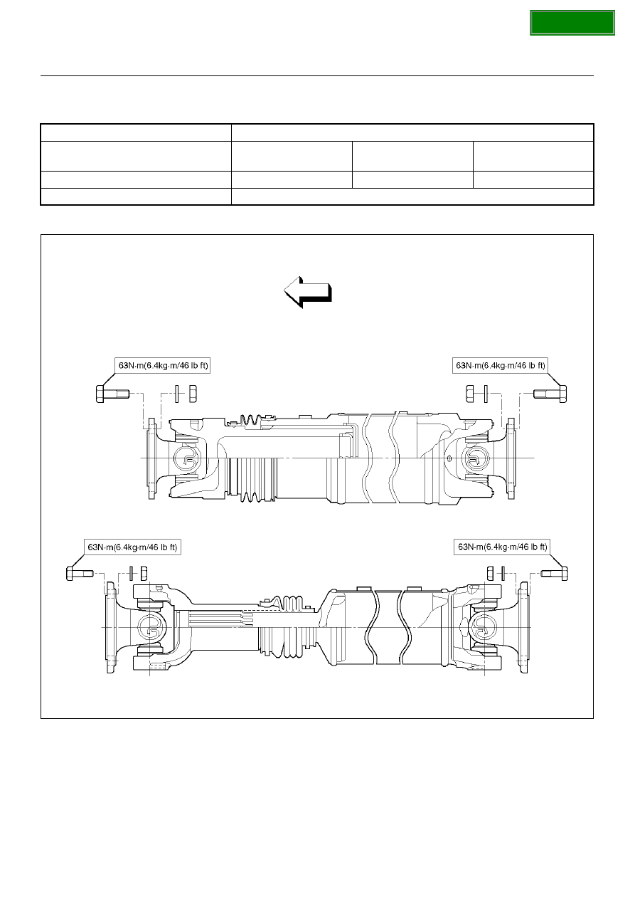
DRIVE SHAFT SYSTEM
Main Data and Specifications
General Specifications
Torque Specifications
E04RX013
4WD Model
Engine (Transmission)
6VD1 (M/T)
6VD1 (A/T·Normal
transfer)
6VD1 (A/T·TOD)
Length (between two frange)
1302.2mm (51.27in)
1133.1mm (44.61in)
1121.9mm (44.17in)
Universal joint type
Cardan type