Content .. 1332 1333 1334 1335 ..
Opel Frontera UE. Manual - part 1334
DRIVE LINE CONTROL SYSTEM (TOD)
4B2–76
Chart B–3
The TOD switch B circuit is shorted to GND or broken.
Function of circuit
—
Fail condition
Even after the transfer mode is selected from TOD to 4L, the indicator lamp state does
not change.
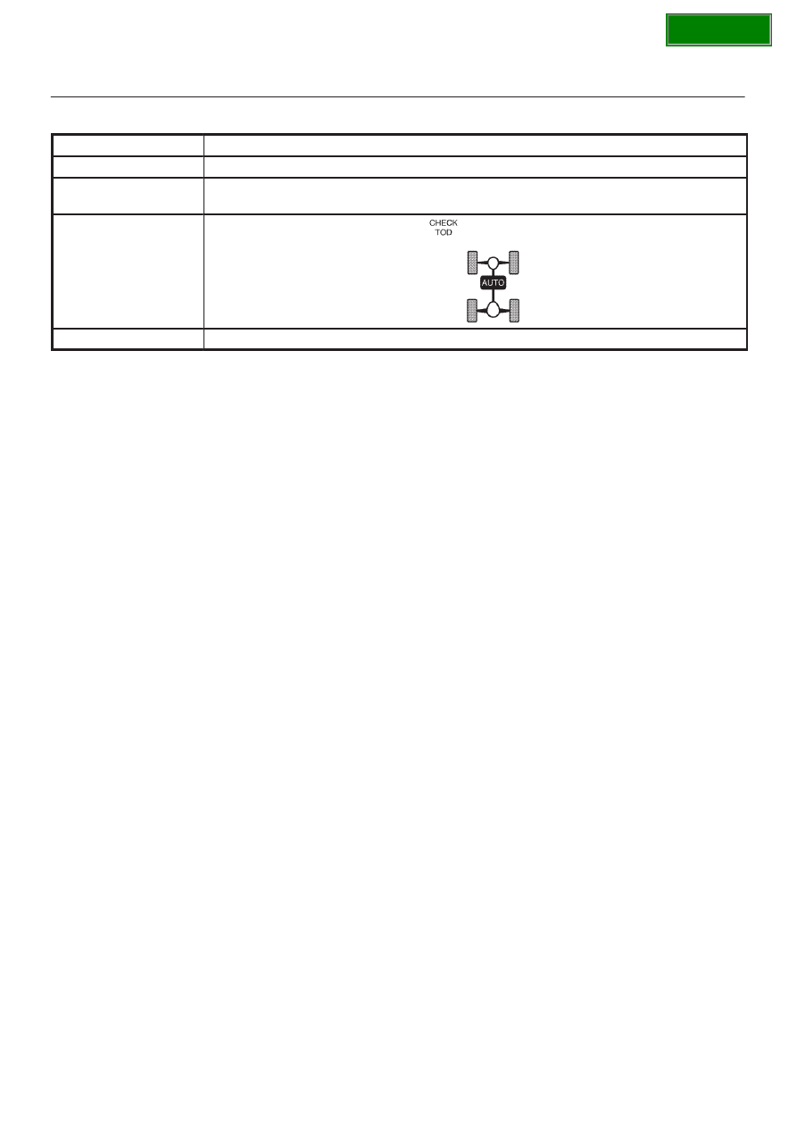
Indicator lamp state
TOD switch position
4L