Opel Frontera UE. Manual - part 1319


  Index      Opel     Opel Frontera UE - service repair manual 1999-2001 year


Search            


Content   ..  1317  1318  1319  1320   ..


Opel Frontera UE. Manual - part 1319


DRIVE LINE CONTROL SYSTEM (TOD)

4B2–16

How to Clear The Trouble Code
The trouble codes saved to the control unit can be deleted
by the following procedure if the starter switch is being in
the OFF position.

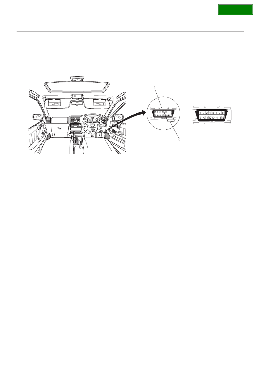
1. Short-circuit terminal 8 of the self-diagnostic

connector to GND (terminal 4 or 5).

2. Turn on the starter switch while maintaining the state

of step1, and stop short-circuiting terminal 8 to GND
within five seconds.

350R100005

Legend

(1) Data Link Connector
(2) Jumper Wire

3. If the conditions shown in steps 1 and 2 are met, the

trouble codes saved to the control unit are cleared.
(After the codes are completely deleted, the code 12
that indicates the normal condition is continuously
displayed.)

Precautions on Diagnosis

Replacement of Control Unit
The control unit itself rarely fails. In most cases, the
harnesses have failed (i.e. short-circuit) to cause
secondary troubles. Other cases include that the cause
has been unknown due to intermittent occurrence of
troubles and the troubles are removed accidentally along
with replacement of control unit, resulting in misjudgment
of cause. Therefore, before replacing the control unit,
check the connector joints and whether the unspecified
current flows in the control unit due to short-circuit
between harnesses.

Trouble Intermittently Observed
Troubles intermittently observed are mostly attributable
to temporary imperfect connection of harnesses and
connectors.
When such troubles are found, check the associated
circuit according to the following procedure.

1. Check whether improper connectors are plugged in

or connector terminals are completely engaged.

2. Check whether the terminals are deformed or

damaged. If yes, remove the deformation or damage
and connect the terminals securely.

3. It is likely that wires in the harness are falsely broken.

Therefore, in examination of failed harness circuit,
shake the harness for check to such extent that the
harness will not be damaged.

Test Run of Failed TOD Vehicle
If the TOD indicator lamps experienced faulty operation
even once in the past, the failed portion can be identified
by use of the procedure “Diagnosis from Trouble Codes”
or “Trouble Diagnosis Depending on the Status of TOD
Indicator”. If the troubles that are only recognized as
abnormal phenomena of the vehicle by the driver are
observed, conduct the test run in the following procedure
to reproduce the faulty phenomena and diagnose the fault
for each phenomenon.

1. Start the engine, and check that the TOD indicator

lamps are turned on for about two seconds for initial
check; the CHECK lamp goes off; and the TOD
indicator lamps display the specified drive mode. (If
the CHECK lamp starts blinking, read the trouble
codes and identify the failed portion.)

SECTION

4B2–17

DRIVE LINE CONTROL SYSTEM (TOD)

2. While keeping the vehicle standstill, operate the TOD

switch to change the modes: 2H mode

TOD

mode

4L mode

TOD mode

2H mode. Check

that the TOD indicator lamps correctly display the
status whenever the mode is changed. If the
transition status is displayed during the shift
operation, run the vehicle a little to complete shifting.

3. Slowly start the vehicle in the TOD mode, and add the

power to accelerate to at least 40 km/h (25 mph)and
maintain the speed for about two minutes. Apply the
brake to completely stop the vehicle. Repeat this test
pattern at least three times.

4. Turn the steering to the right end (or left end) in the

TOD mode, and slowly start the vehicle and make a
circle five times. Next, conduct the same test in the 2H
mode.

5. Slowly start the vehicle in the TOD mode, and

accelerate to at least 40 km/h (25 mph). Keep the
established speed, carefully change the mode in the
sequence “TOD mode

2H mode 

TOD mode”

while checking that the shift is complete in each mode
change. After the test, apply the brake to completely
stop the vehicle.

6. Slowly start the vehicle in the TOD mode, and

accelerate to at least 40 km/h (25 mph). Apply the
brake strongly so that the ABS works, and completely
stop the vehicle.

7. Slowly start the vehicle in the 4L mode, and

accelerate to at least 20 km/h (13 mph). Apply the
brake to completely stop the vehicle.

If the CHECK lamp starts blinking during the test run, read
the trouble codes and give appropriate maintenance
according to the diagnostic procedure. If the TOD
indicator lamps are lit abnormally during the run, check
the lighting condition and give appropriate maintenance
according to the diagnostic procedure. Even if the
phenomena are not observed, try to reproduce the
abnormal state reported by the customer to the possible
extent.

Post-Repair Check
As long as the starter is not turned off, the TOD indicator
lamps continue blinking even after the failed portion is
repaired. Therefore, upon completion of repair, be sure to
turn off the starter switch once and then turn on it to
conduct the test run sequence specified in steps 1
through 7 above and check that the TOD indicator lamps
no longer show any faulty status.

SECTION

DRIVE LINE CONTROL SYSTEM (TOD)

4B2–18

Basic Diagnostic Flow Chart

C07R100011

SECTION

4B2–19

DRIVE LINE CONTROL SYSTEM (TOD)

Parts Location

D04R100023

Legend

(1) C–36
(2) H–13, H–14
(3) C–34
(4) I–53
(5) I–9
(6) I–10
(7) H–16, H–17

(8) C–16
(9) H–5, H–39

(10) A–1

(11) H–38

(12) A–2
(13) C–62
(14) C–59
(15) C–60

SECTION


Content   ..  1317  1318  1319  1320   ..