Content .. 1286 1287 1288 1289 ..
Opel Frontera UE. Manual - part 1288
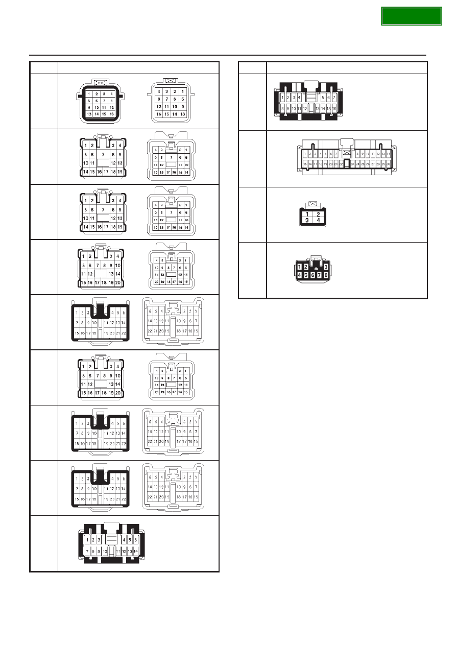
INTELLIGENT SUSPENSION
3F–15
No.
Connector face
H-6
H-13
H-14
H-15
H-16
H-17
H-40
H-42
I-2
No.
Connector face
I-9
I-10
I-18
I-55
|
|
|
Content .. 1286 1287 1288 1289 ..
INTELLIGENT SUSPENSION 3F–15 No. Connector face H-6 H-13 H-14 H-15 H-16 H-17 H-40 H-42 I-2 No. Connector face I-9 I-10 I-18 I-55 |