Opel Frontera UE. Manual - part 1248


  Index      Opel     Opel Frontera UE - service repair manual 1999-2001 year


Search            


Content   ..  1246  1247  1248  1249   ..


Opel Frontera UE. Manual - part 1248


HEATING, VENTILATION AND AIR CONDITIONING (HVAC)

1A–113

As shown above, display of result along nine items is
repeated with 3-second interval in between.
Note 1: When checking the solar radiation sensor, apply
sufficient light using a 60W bulb. Otherwise, it can be
diagnosed as failed.
Note 2: If the temperature setting lever is set on both

ends (one set to 18

°

C, blue scale =  Full cool and the

other to 31

°

C, red scale = Full hot), they can be

diagnosed as failed.
Note 3: Likewise, the fan switch can be diagnosed as
failed if set on both ends.

*

2

Displaying the Past Trouble Diagnosing Table

The past trouble diagnosis displays only the items on
which trouble has recurred 16 times in the past.
If you press the air conditioning switch once while the
current trouble diagnosis is taking place, display of the
past trouble diagnosis will appear on the indicator lamp
(LED) of the air conditioning switch.
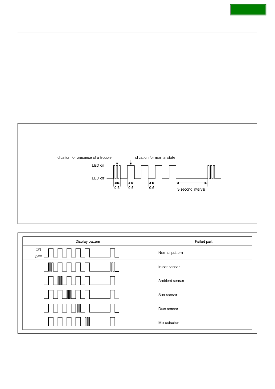
Results of the diagnosis along the following five items

are displayed one by one in 0.5 second interval
irrespective of presence or absence of a trouble. A failed
item is indicated by flashing of the LED that is repeated
3 times within 0.5 seconds. You can locate the failed
section by counting in what sequence it has been
displayed.

F01RX011

F01RY00007

SECTION

1A–114

HEATING, VENTILATION AND AIR CONDITIONING (HVAC)

*

3

Check of Output Equipment

F01RX015

SECTION

HEATING, VENTILATION AND AIR CONDITIONING (HVAC)

1A–115

Inspection By Failed Location

Inspection of the Sensors

When the self-diagnosis function has determined that
trouble is present on the sensors, check them according
to the following flow chart.

F01RY00005

SECTION

1A–116

HEATING, VENTILATION AND AIR CONDITIONING (HVAC)

Chart 1: In Car Sensor

D08RY00888

Step

Action

Value(s)

Yes

No

Disconnect the in car sensor connector. (No.I-4)
Is performance of the sensor normal? (Refer to the
later section on “Individual Inspection")

Go to Step 2

Replace the in 

car sensor

Is there continuity between the harness side
connector No.I44–1 and No.I4–3?

Go to Step 4

Go to Step 3

Repair an open circuit between terminal No.I44–1 and
No.I4–3.
Is the action complete?

Go to Step 2

Is there continuity between the harness side
connector No.I44–11 and No.I4–4?

Go to Step 6

Go to Step 5

Repair an open circuit between terminal No.I44–11
and No.I4–4.
Is the action complete?

Go to Step 4

Replace the auto air conditioner control unit.
Is the action complete?

Verify repair

SECTION


Content   ..  1246  1247  1248  1249   ..