Content .. 1219 1220 1221 1222 ..
Opel Frontera UE. Manual - part 1221
HEATING, VENTILATION AND AIR CONDITIONING (HVAC)
1A–5
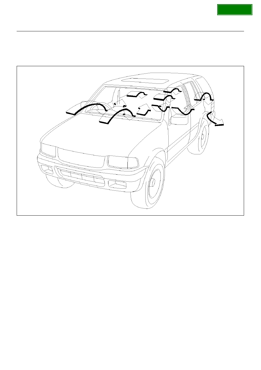
Ventilation
Setting the air source select lever to “FRESH" position
allows the heating system to work with sending the
fresh air from outside.
The blower fan also serves to deliver fresh outside air to
the passenger compartment to assure adequate
ventilation.
810RW319