Index Opel Opel Frontera UE - service repair manual 1999-2001 year
Search
Content .. 1184 1185 1186 1187 ..
Opel Frontera UE. Manual - part 1186
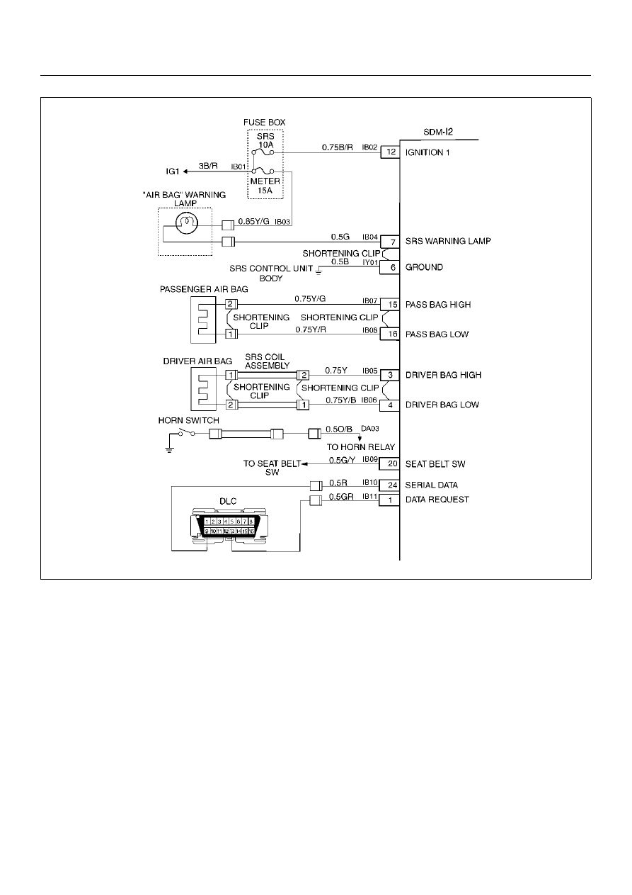
SUPPLEMENTAL RESTRAINT SYSTEM
9J–3
D09RX002