Content .. 1145 1146 1147 1148 ..
Opel Frontera UE. Manual - part 1147
BODY STRUCTURE
8F–19
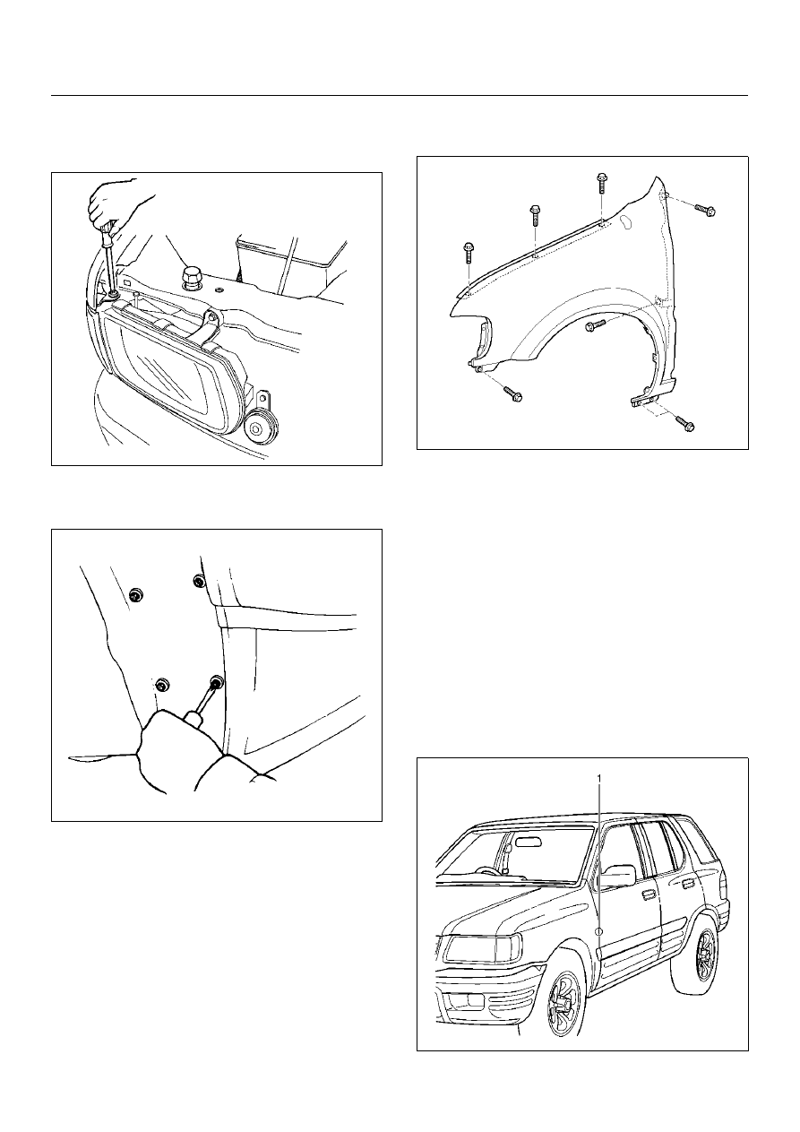
3. Remove the front turn signal light assembly.
• Remove the fixing screws and disconnect the
connector.
801RY00005
4. Remove the front mud flap.
5. Remove the inner liner.
647RY00003
6. Remove the antenna assembly.
• Refer to Rod Type Antenna in Entertainment
section.
7. Remove the side turn signal light.
• Refer to Side Turn Signal Light Bulb in Lighting
System section.
8. Remove the front fender panel.
• Remove the eight fixing bolts.
614RX006
9. Remove the front wheel arch moulding (If so
equipped).
• Refer to Wheel Arch Moulding in Exterior/Interior
Trim section.
Installation
To install, follow the removal steps in the reverse order,
noting the following points:
1. Tighten the front fender panel fixing bolts to the
specified torque.
Torque : 7 N·m (0.7 kg·m/61 lb in)
2. Check the fender and front door(1).
Clearance: 5.0 mm (0.196 in)
Height (step): Flush
610RY00015