Content .. 1102 1103 1104 1105 ..
Opel Frontera UE. Manual - part 1104
8D–127
WIRING SYSTEM
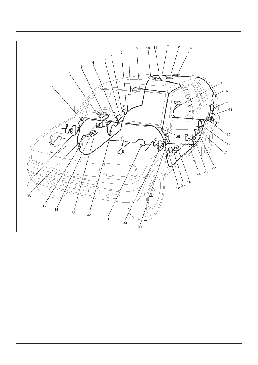
Parts Location
D08RWD17
Legend
(1) Relay & Fuse Box
(2) FRT Door SW–RH
(3) B–1
(4) D–24
(5) RR Courtesy–Light–RH
(6) B–21
(7) RR Door SW–RH
(8) Map Light
(9) L–2
(10) Dome Light
(11) L–3
(12) B–11 (4Door Model)
(13) Luggage Room Light
(14) G–13 (2Door Model)
(15) G–1
(16) H–37
(17) Tailgate Switch
(18) B–20
(19) H–22
(20) RR Door SW–LH
(21) B–16
(22) RR Courtesy–Light–LH
(23) H–29
(24) FRT Door SW–LH
(25) H–30
(26) FRT Courtesy–Light–LH
(27) D–18
(28) H–33
(29) I–26
(30) I–41, I–42
(31) B–8
(32) H–24
(33) FRT Courtesy–Light–RH
(34) D–7
(35) H–28
(36) I–46
(37) H–19, H–32