Content .. 1055 1056 1057 1058 ..
Opel Frontera UE. Manual - part 1057
CLUTCH
7C–19
Driven Plate Warpage
1. Insert the clutch pilot aligner J–24547 into the driven
plate splined hub. The clutch pilot aligner must be
held perfectly horizontal.
2. Set a dial indicator to the driven plate outside
circumference.
3. Slowly turn the driven plate. Read the dial indicator as
you turn the driven plate. If the measured value
exceeds the specified limit, the driven plate assembly
must be replaced.
Driven Plate Warpage
Standard: 0.7mm (0.028in)
Limit: 1.0mm (0.039in)
201RS008
Driven Plate Splined Hub Spline Wear
1. Clean the driven plate splined hub.
2. Install the driven plate to the transmission top gear
shaft spline.
3. Set a surface gauge to the driven plate outside
circumference.
4. Slowly turn the driven plate counterclockwise.
Measure the spline rotation play as you turn the
driven plate. If the measured value exceeds the
specified limit, the driven plate assembly must be
replaced.
Driven Plate Warpage
Standard: 0.5mm (0.020in)
Limit: 1.0mm (0.039in)
201RS009
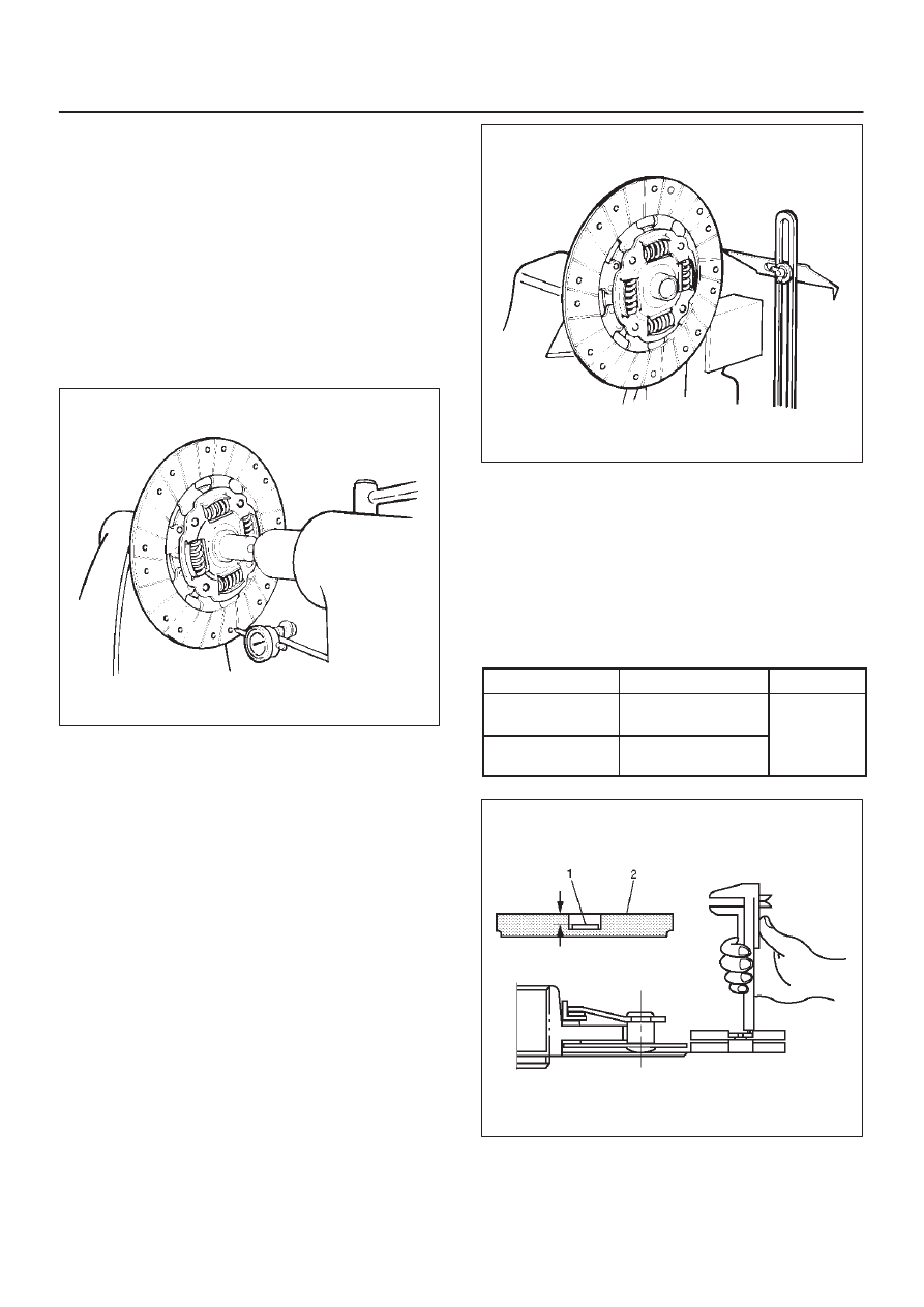
Rivet Head Depression
D
Use a depth gauge or a straight edge with steel rule to
measure the rivet head depression (1) from the facing
surface (2).
D
Be sure to measure the rivet head depression on both
sides of the driven plate. If the measured value is less
than the specified limit, the driven plate assembly
must be replaced.
Rivet Head Depression
Standard
Limit
Fly wheel side
1.2–1.8mm
(0.047–0.071in)
0.2mm
Pressure plate
side
1.6–2.2mm
(0.062–0.087in)
(0.008in)
201RS010