Opel Frontera UE. Manual - part 1023


  Index      Opel     Opel Frontera UE - service repair manual 1999-2001 year


Search            


Content   ..  1021  1022  1023  1024   ..


Opel Frontera UE. Manual - part 1023


TRANSMISSION CONTROL SYSTEM (4L30–E)

7A1–17

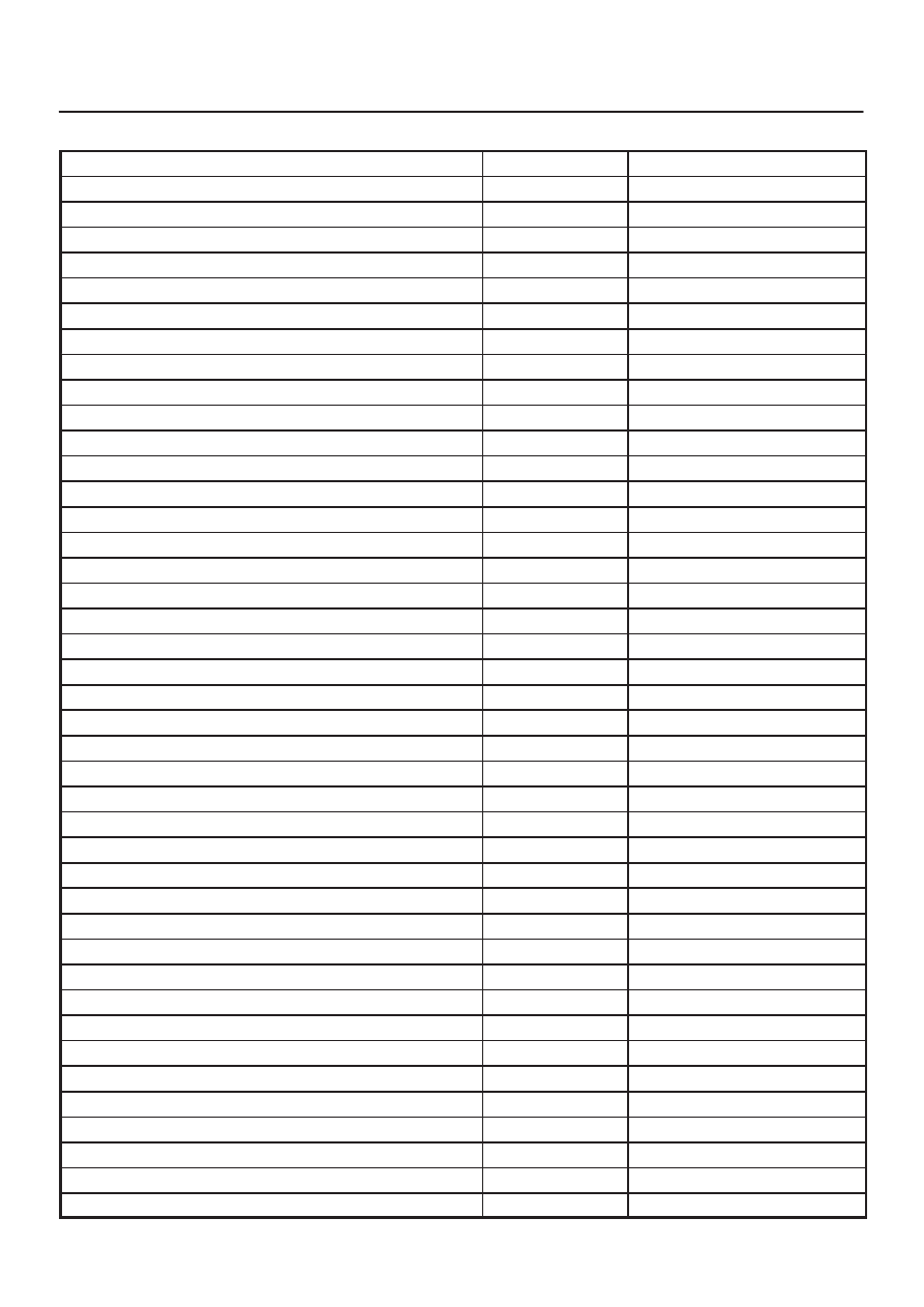
F0: Transmission Data

Item

Unit

Engine running at idle

Engine Speed

RPM

750 

 900 RPM

Vehicle Speed

km/h, MPH

0 MPH

Throttle Position

%

0 %

Throttle Position Sensor

V

0.5 

 1.0 V

Manifold Absolute Pressure

kPa

approx. 40 kPa

Barometric Pressure

kPa

approx. 102 kPa

AT Output Speed (Automatic Transmission)

RPM

0 RPM

AT Input Speed Ratio (Automatic Transmission)

0.0

Ignition Voltage

V

12.8 

 14.1 V

AT Oil Temperature (Automatic Transmission)

°

C, 

°

F

70 

 80

°

C (158 

 176

°

F)

AT Oil Life Monitor (Automatic Transmission)

%

100 %

Commanded Gear

1

Current Gear

1

Mode Switch C

Inactive, Active

Inactive

Mode Switch B

Inactive, Active

Inactive

Mode Switch A

Inactive, Active

Active

Mode Switch G

Inactive, Active

Active

Actual Gear

Park

1–2 Shift Solenoid A

Off, On

Off

2–3 Shift Solenoid B

Off, On

On

Brake Switch

Off, On

Off

Solenoid Brake Band

Off, On

Off

TCC Slip Speed

RPM

750 

 900 RPM

TCC Status

Disabled, Enabled

Enabled

TCC Solenoid

Off, On

Off

TCC Duty Cycle

%

0 %

TCC Apply Mode

No Apply, In Apply

No Apply

TCC Release Mode

No, Yes

No

TCC On Mode

No, Yes

No

TCC Off Mode

No, Yes

Yes

Default Gear

No, Yes

No

Engine Warm

No, Yes

Yes

A/C Request

Yes, No

Yes

A/C Clutch Relay

Off, On

On

Winter Switch

Off, On

Off

Winter Drive Lamp

Off, On

Off

Kickdown Switch

Off, On

Off

ATF Lamp (Automatic Transmission)

Off, On

Off

Power Switch

Normal, Power

Normal

Power Drive Lamp

Off, On

Off

ABS Status

On, Off

(Not used)

7A1–18 TRANSMISSION CONTROL SYSTEM (4L30–E)

F1: PC Solenoid Data

Item

Unit

Engine running at idle

Engine Speed

RPM

750 

 900 RPM

Vehicle Speed

km/h, MPH

0 MPH

Throttle Position

%

0 %

Throttle Position Sensor

V

0.5 

 1.0 V

Manifold Absolute Pressure

kPa

approx. 40 kPa

Barometric Pressure

kPa

approx. 102 kPa

PCS Current (Pressure Control Solenoid)

A

approx. 1.0 A

PCS Actual Current (Pressure Control Solenoid)

A

approx. 1.0 A

PCS Duty Cycle (Pressure Control Solenoid)

%

approx. 45 %

Desired PCS Pressure (Pressure Control Solenoid)

kPa

43 

 52 kPa

Shift Pressure (Line Pressure)

kPa

43 

 52 kPa

Transmission Temperature

°

C, 

°

F

75 

 110

°

C (167 

 230

°

F)

TRANSMISSION CONTROL SYSTEM (4L30–E)

7A1–19

Flashing Code

1. A DTC (Flashing Code) can be displayed by the

Powertrain Control Module (PCM) by shorting
together terminals 6 and 4 or 5 (GND) of the Data Link
Connector (DLC) located right side of the drivers side
instrument panel.

810RW317

821RY00065

2.

1. In case there is no DTC stored in memory. The

CHECK ENGINE indicator flashes Normal Code
“12” repeatedly.

2. In case there is DTC stored in memory. First,

Normal Code “12” is displayed three times and
then any other DTC‘s are displayed three times.

When all DTC‘s have been displayed they are
displayed again beginning from the first one.

3. Write down all codes numbers and GOTO DTC

CHECK.

C07RX006

7A1–20 TRANSMISSION CONTROL SYSTEM (4L30–E)

OBD II Diagnostic Management System

Powertrain Control Module (PCM) Location

828RX004

Class 2 Serial Data Bus
OBD II technology requires a much more sophisticated
PCM than does OBD I technology. The OBD II PCM
diagnostic management system not only monitors
systems and components that can impact emissions, but
they also run active tests on these systems and
components. The decision making functions of OBD II
PCM have also greatly increased. To accommodate this
expansion in diagnostic complexity, Isuzu engineers have
designed the Class 2 serial data bus, which meets SAE
J1850 recommended practice for serial data.
“Serial Data” refers to information which is transferred in a
linear fashion – over a single line, one bit at a time. A “Data
Bus” is an electronic pathway through which serial data
travels.

FRONTERA previously used a 5 volt data bus called
UART, which is an acronym for “Universal Asynchronous
Receive and Transmit”. When neither the vehicle’s
control module nor the diagnostic tool, such as a Tech 2,
are “talking,” the voltage level of the bus at rest is 5 volts.
The two computers talk to each other at a rate of 8,192
bits per second, by toggling or switching the voltage on
the data bus from 5 volts to ground.
Class 2 data, which is used on OBD II vehicles, is quite
different. Data is transferred at a rate of 10.4 kilobits per
second, and the voltage is toggled between zero and 7
volts.


Content   ..  1021  1022  1023  1024   ..