Opel Frontera UE. Manual - part 71


  Index      Opel     Opel Frontera UE - service repair manual 1999-2001 year


Search            


Content   ..  69  70  71  72   ..


Opel Frontera UE. Manual - part 71


DIFFERENTIAL (FRONT)

4A1–5

Front Drive Axle Assembly

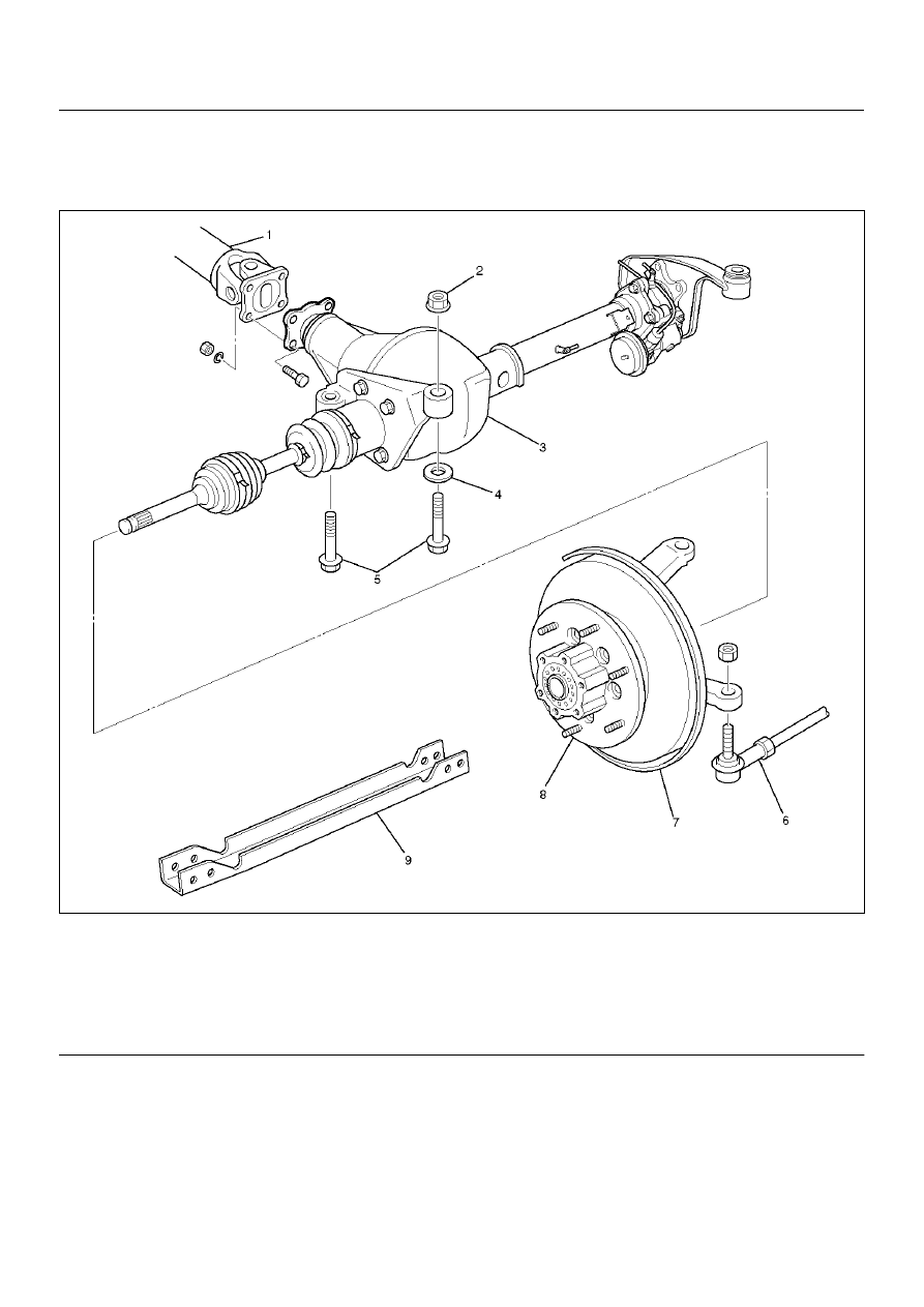
Front Drive Axle Assembly and Associated Parts

412RX010

Legend

EndOFCallout

(1) Propeller Shaft
(2) Mounting Nut
(3) Front Axle Case Assembly and Front Drive 

Shaft Assembly

(4) Washer

(5) Mounting Bolt
(6) Tie–rod End; Power Steering Unit
(7) Knuckle and Back Plate
(8) Hub and Disc Assembly
(9) Suspension Crossmember

4A1–6

DIFFERENTIAL (FRONT)

Removal

1. Jack up the vehicle and support it using jack stand.

2. Remove the tire and wheel.

3. Remove the stone guard.

4. Remove the brake caliper fixing bolt and hang the 

caliper.  Refer to Disc Brakes in Brake section.

5.  Remove the antilock brake system speed sensor.

 Refer to Front Wheel Speed Sensor in Brake 
section.

6.  Remove the hub and disc assembly.

 Refer to Front Hub and Disc in this section.

7. Remove the propeller shaft, refer to Front Propeller 

Shaft in this section.

8. Loosen the height control arm of the torsion bar, 

then remove the torsion bar from lower control arm.
refer to Torsion Bar in Suspension section.

9. Remove the suspension crossmember.

10. Remove the lower nut (1) of the stabilizer link.

11. Remove the lower bolt and nut (2) of the shock 

absorber.

412RW057

12. Remove the tie-rod end from the knuckle.  Refer to 

Power Steering Unit in Steering Section.

13. Disconnect the hose of the shift on the fly, at the 

hose clip portion (1).

14. Disconnect the shift switch connector (2).

412RW058

15. Remove the bolts and nuts of the lower control arm 

(Frame side), then disconnect the lower control arm 
from frame.

16. Disconnect between the right side upper control arm 

and the knuckle, then remove the knuckle with lower 
control arm.

CAUTION:  When removing the knuckle, be careful 
not to damage the oil seal inside of the knuckle.

410RW008

DIFFERENTIAL (FRONT)

4A1–7

17. Support the differential case by the jack.

18. Remove the front axle mounting bolts and nuts, 

lower the jack slowly.  Remove the left side drive 
shaft end from the knuckle, then lower the axle 
assembly from the vehicle.

CAUTION:

1. During the work, be sure that the axle assembly 

is supported securly.

2. Be careful not to damage the bellows of the 

power steering unit by interference.

3. Be careful not to damage the hose bracket of the 

shift on the fly by interference.

Installation

1. Support the differential case by the jack.

2. Jack up the front drive axle assembly, install the left 

side drive shaft to the knuckle, then install the mount 
bolts and nuts.

CAUTION:

1. Be careful not to damage the bellows of the 

power steering unit by interference.

2. Be careful not to damage the hose bracket of the 

shift on the fly by interference.

3. When installing the drive shaft to the knuckle, 

be careful not to damage the oil seal inside of 
the knuckle.

3. Tighten the mounting bolts and nuts to the specified 

torque.

Torque:168N·m (17.2kg·m/124 lbft)

412RX011

4. Install the right side knuckle with lower control arm 

to the upper control arm.
Refer to Knuckle in Suspension section.

CAUTION:  When insert the drive shaft to the 
knuckle, be careful not to damage the oil seal inside 
of the knuckle.

5. Align the bolt hole of the lower control arm, install 

the bolts and nuts.

NOTE:  Adjust the buffer clearance before tighten the 
bolts and nuts of the lower control arm.

6. Install the hose of the shift on the fly (1).

7. Install the shift switch connector (2) of the shift on 

the fly.

412RW058

8. Install the tie-rod end of the power steering unit to 

the knuckle, tighten the nut to the specified torque.

Torque:118N·m (12.0kg·m/87 lbft)

9. Install lower bolts and nuts of the shock absorber, 

tighten it to the specified torque.

Torque:93 N·m (9.5kg·m/69 lbft)

10. Install lower nuts of the stabilizer link, tighten it to 

the specified torque.

11. Install the suspension crossmember.

12. Install the torsion bar.

Refer to Torsion Bar in Suspension section.

13. Install the front propeller shaft.

Refer to Front Propeller Shaft in this section.

14. Install the hub and disc assembly and adjust the 

bearing preload.
Refer to Front Hub and Disc in this section.

15. Install the wheel speed sensor of the antilock brake 

system.

16. Install the brake caliper.  Tighten the bolt of the 

caliper bracket to the specified torque.

Torque:50 N·m (5.1kg·m/37 lbft)

17. Install the stone guard.

18. Install the tire and wheel.

19. Lower the vehicle, adjust the trim height.

Refer to Trim Height Adjustment in Steering section.

20. Tighten the bolts and nuts of the lower control arm 

to the specified torque.
Refer to Lower Control Arm in Suspension section.

4A1–8

DIFFERENTIAL (FRONT)

Differential Assembly

Disassembled View

415RX003

Legend

EndOFCallout

(1) Differential Assembly
(2) Flange Nut
(3) Flange
(4) Dust Cover
(5) Oil Seal
(6) Outer Bearing 
(7) Outer Bearing Outer Race
(8) Differential Carrier
(9) Bearing Cap

(10) Bolt
(11) Inner Bearing Outer Race

(12) Collapsible Spacer
(13) Pinion Gear
(14) Inner Bearing
(15) Adjust Shim
(16) Diff Cage Assembly
(17) Side Bearing Outer Race
(18) Side Bearing
(19) Adjust Shim
(20) Bolt
(21) Axle Case


Content   ..  69  70  71  72   ..