Opel Frontera UE. Manual - part 47


  Index      Opel     Opel Frontera UE - service repair manual 1999-2001 year


Search            


Content   ..  45  46  47  48   ..


Opel Frontera UE. Manual - part 47


2A–16

POWER-ASSISTED STEERING SYSTEM

Toe-in Adjustment

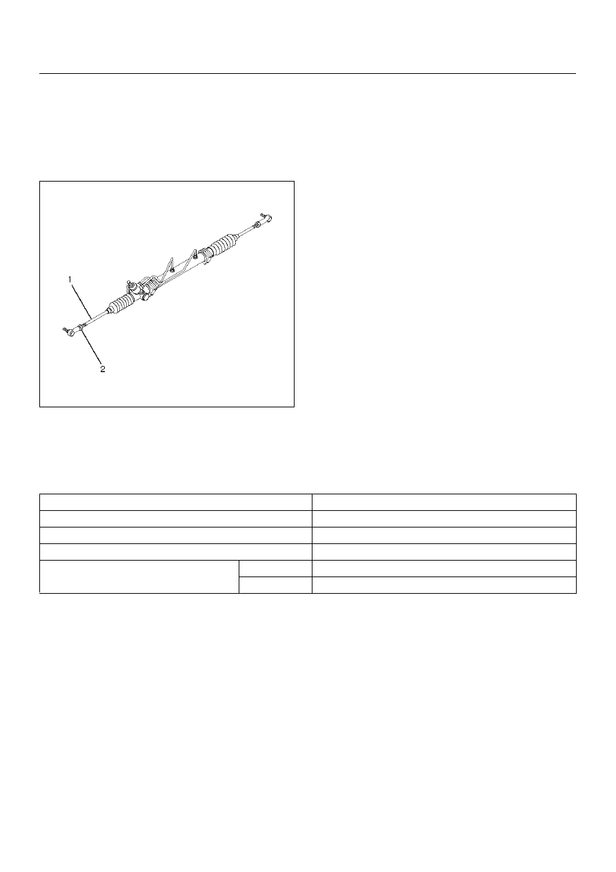
1. To adjust the toe-in angle, loosen the lock nuts (2) 

on the tie rod (1) and turn the tie rod.  Turn both rods 
the same amount, to keep the steering wheel 
centered .

Toe-in: 0 

±±±±

 2 mm (0 

±±±±

 0.08in)

433RW006

2. Tighten the lock nut to the specified torque.

Torque: 98N·m (10.0kg·m/72lbft)

Main Data and Specifications

General Specification

Caster

2

°

30' 

±

 1

°

Camber

0

°


±

 30'

King pin inclination

12

°

30' 

±

 30'

Toe-in 0 

±

 2 mm (0 

±

 0.08 in)

Max. steering angle

inside

32.6

°

 (+0

°

30' to –2

°

30' )

outside

31.8

°

POWER-ASSISTED STEERING SYSTEM

2A–17

Torque Specification

E02RX006

Special Tools

ILLUSTRATION

TOOL NO.

TOOL NAME

5–8840–0135–0

(J–29877–A)

Tester;

Power steering

5–8840–2297–0

(J–39213)

Adapter;

Power steering tester

ILLUSTRATION

TOOL NO.

TOOL NAME

2A–18

POWER-ASSISTED STEERING SYSTEM

Power Steering Unit

Power Steering Unit and Associated Parts

431RW026

Legend

EndOFCallout

Removal

1. Remove the stone guard.

2. Remove the transfer gear assembly.

Make a setting mark across the coupling flange and 
steering unit to ensure reassembly of the parts in 
the original position.

3. Drain power steering fluid.

4. Remove the tie rod end assembly from knuckle.

Use tie rod end remover 5–8840–2005–0.

901RW270

(1) Bracket
(2) Transfer Gear Assembly

(3) Power Steering Unit Assembly
(4) Crossmember

POWER-ASSISTED STEERING SYSTEM

2A–19

5. Disconnect the feed line and return line from 

steering unit.
Remove the clips on the crossmember and frame.
Wire the power steering line to frame. 

NOTE:  Take care to prevent foreign matter from entry 
when disconnect the power steering line.

6. Remove the torsion bar.  Refer to Front Suspension 

in Suspension section.

7. Remove the lower control arm bolt (Frame side).

Refer to Front Suspension in Suspension section.

8. Apply a setting mark across the crossmember and 

frame so parts can be reassembled in their original 
position.

431RX013

9. Remove the crossmember fixing bolt.

10. Remove the power steering unit with the 

crossmember.

11. Remove the power steering unit.

Installation

1. Install power steering unit to crossmember.

Tighten fixing bolt to specified torque.

Torque: 116N·m (11.8kg·m/85 lbft)

2. Install power steering unit with crossmember to 

frame by aligning the setting marks made when 
removing.
Tighten crossmember mounting bolt to specified 
torque.

Torque: 190N·m (19.4kg·m/140lbft)

3. Install lower control arm bolt.

Refer to Front Suspension in Suspension section.

4. Install torsion bar.

Refer to Front Suspension in Suspension section.

5. Connect the feed line and return line.

Torque: 25N·m (2.5kg·m/18lbft)

6. Install tie-rod end assembly to knuckle.

Torque: 118N·m (12.0kg·m/87lbft)

7. Install transfer gear assembly.

Align the setting marks made at removal.

Torque: 31N·m (3.2kg·m/23lbft)

8. Install the stone guard.

9. Bleed the system.

Refer to Bleeding the Power Steering System in this 
section.


Content   ..  45  46  47  48   ..