Opel Frontera UE. Manual - part 41
1A–136
HEATING, VENTILATION AND AIR CONDITIONING (HVAC)
Individual Inspection
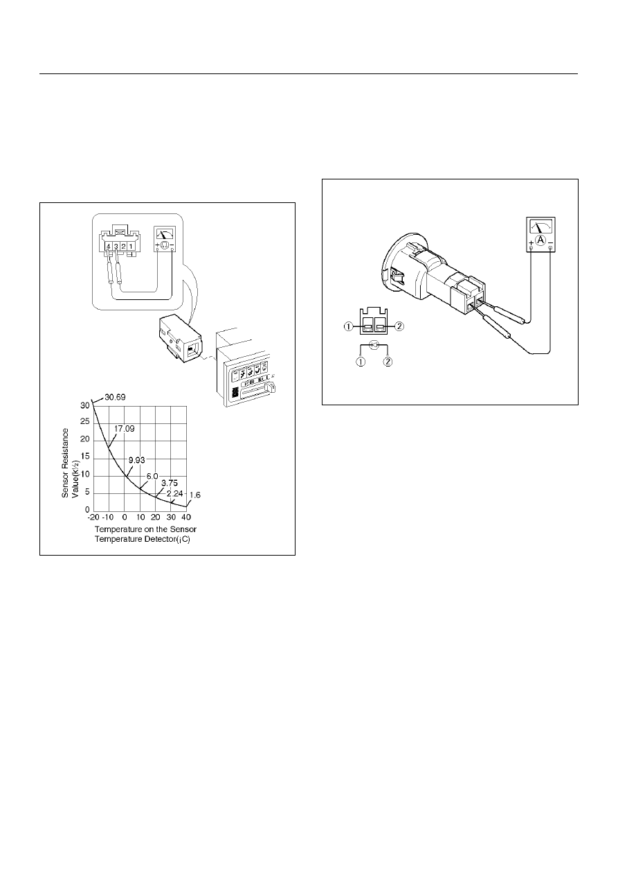
Interior Temperature Sensor
1. Disconnect the interior temperature sensor
connector (I–4).
2. Measure resistance between the interior
temperature sensor side terminal No.I4–3 and
No.I4–4.
865RX007
Solar Radiation Sensor
1. Disconnect the solar radiation sensor connector (I–
50).
2. Measure the current value on the solar radiation
sensor when placed it approximately 15 cm away
from 60W incandescent lamp.
C01RX013