Opel Frontera UE. Manual - part 24


  Index      Opel     Opel Frontera UE - service repair manual 1999-2001 year


Search            


Content   ..  22  23  24  25   ..


Opel Frontera UE. Manual - part 24


1A–68

HEATING, VENTILATION AND AIR CONDITIONING (HVAC)

Main Data And Specifications

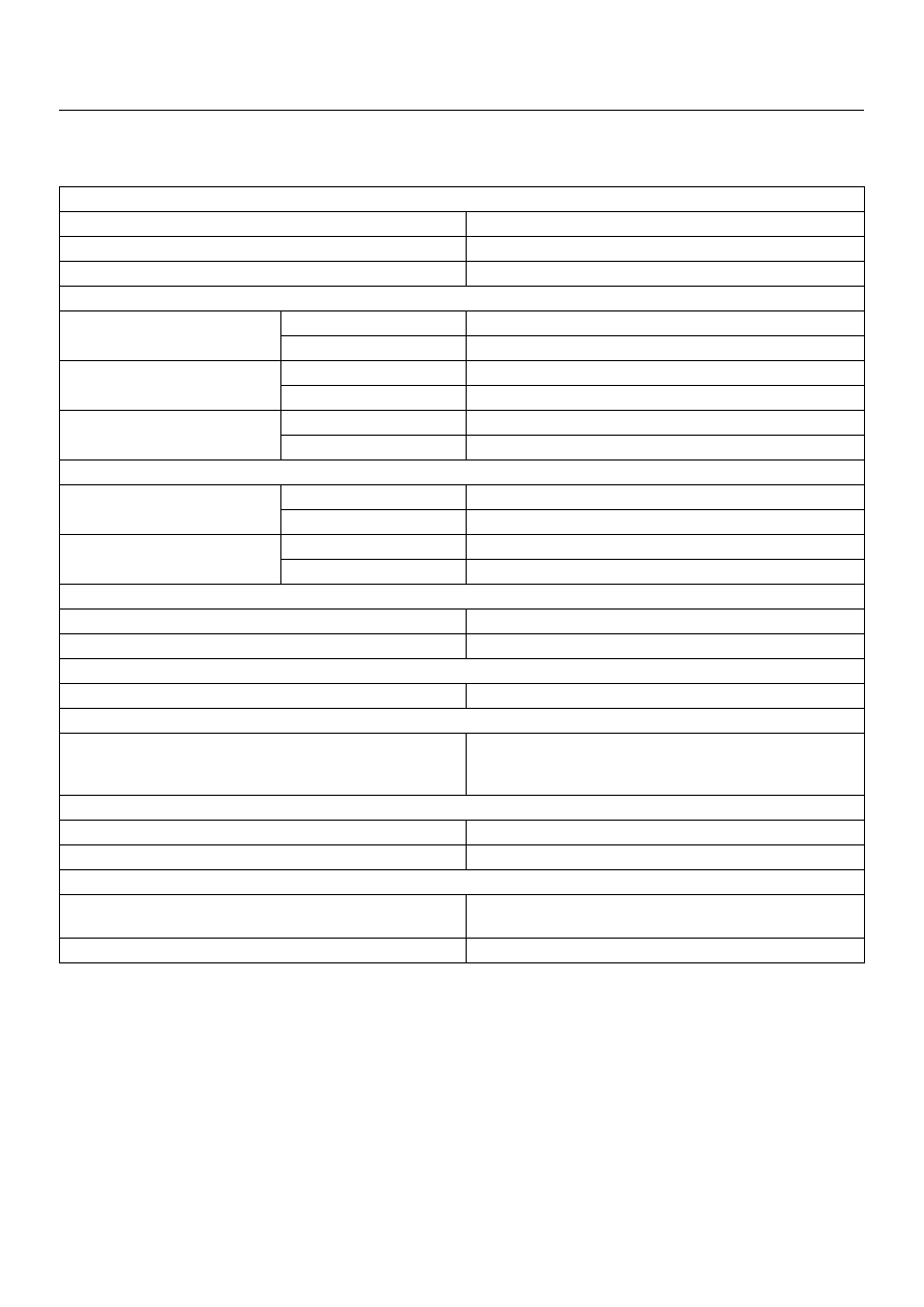
General Specifications

Heater Unit

Temperature control

Reheat air mix system

Capacity

3,700 Kcal./hr.

Air flow

280 m

3

/h

HEATER CORE

Type

AUTO A/C

Plate and corrugate-fin type

MANU A/C

Fin and tube type

Element dimension

MANU A/C

161 mm (6.3) 

× 

163 mm (6.4 in.) 

×

 45 mm (1.8 in.)

AUTO A/C

171 mm (6.7) 

× 

161 mm (6.3 in.) 

×

 25 mm (1 in.)

Radiating area

MANU A/C

Approx. 2.1 m

2

AUTO A/C

Approx. 1.3 m

2

EVAPORATOR ASSEMBLY

Capacity

AUTO A/C

4,100 Kcal./hr.

MANU A/C

4,200 Kcal./hr.

Air flow

AUTO A/C

430 m

3

/hr

MANU A/C

470 m

3

/hr

EVAPORATOR CORE

Type

Al-laminate louver fin type

Element dimension

235 mm (9.3 in.) 

×

 224 mm (8.8 in.) 

×

 60 mm (2.4 in.)

EXPANSION VALVE

Type

Internal pressure equalizer type

THERMOSTAT SWITCH

Type

Electronic thermostat

OFF: Below 0.5 

±

 0.5 

°

C (32.9 

±

 0.9 

°

F)

ON: Above 4.5 

±

 0.5 

°

C (40.1 

±

 0.9 

°

F)

CONDENSER

Type

Parallel flow type

Radiation performance

9,400 Kcal./hr

RECEIVER/DRIER

Type

Assembly includes sight glass with dual (triple) pressure 
switch (V6) or pressure sensor (L14)

Internal volume

300 cc (10 fl.oz.)

HEATING, VENTILATION AND AIR CONDITIONING (HVAC)

1A–69

PRESSURE SWITCH

Type

Dual pressure switch

Low pressure control

ON: 186.3

±

29.4 kPa (27.0

±

4.3 psi)

OFF: 176.5

±

24.5 kPa (25.6

±

3.6 psi)

High pressure control

ON: 2353.6

±

196.1 kPa (341.3

±

28.4 psi)

OFF: 2942.0

±

196.1 kPa (426.6

±

28.4 psi)

Triple pressure switch (V6, A/T)

Low pressure control

ON: 196.3

±

29.4 kPa (27.0

±

4.3 psi)

OFF: 176.5

±

19.6 kPa (25.6

±

2.8 psi)

Medium pressure control

ON: 1471.0

±

98.1 kPa (213.3

±

14.2 psi)

OFF: 1078.7

±

117.7 kPa (156.4

±

17.7 psi)

High pressure control

ON: 2353.6

±

196.1 kPa (341.3

±

28.4 psi)

OFF: 2942.0

±

196.1 kPa (426.6

±

28.4 psi)

REFRIGERANT

Type

HFC-134a

Specified amount

650 g (1.43 lbs.)

1A–70

HEATING, VENTILATION AND AIR CONDITIONING (HVAC)

Torque Specifications

E06RX006

E06RX007

HEATING, VENTILATION AND AIR CONDITIONING (HVAC)

1A–71

Compressor

Service Precaution

WARNING:  This vehicle has a Supplemental
Restraint System (SRS). Refer to the SRS
Component Location View in order to determine
whether you are performing service on or near the
SRS components or the SRS wiring. When you are
performing service on or near the SRS components
or the SRS wiring, refer to the SRS On-Vehicle
Service Information. Failure to follow CAUTIONS
could result in possible air bag deployment,
personal injury, or otherwise unneeded SRS system
repairs.

CAUTION:  Always use the correct fastener in the
proper location. When you replace a fastener, use
ONLY the exact part number for that application.
ISUZU will call out those fasteners  that require a
replacement after removal. ISUZU will also call out
the fasteners that require thread lockers or thread
sealant. UNLESS OTHERWISE SPECIFIED, do not
use supplemental coatings (paints, greases, or
other corrosion inhibitors) on threaded fasteners or
fastener joint interfaces. Generally, such coatings
adversely affect the fastener torque and the joint
clamping force, and may damage the fastener. When
you install fasteners, use the correct tightening
sequence and specifications. Following these
instructions can help you avoid damage to parts
and systems.

General Description

When servicing the compressor, keep dirt or foreign
material from getting on or into the compressor parts
and system.  Clean tools and a clean work area are
important for proper service.  The compressor
connections and the outside of the compressor should
be cleaned before any "On-Vehicle" repair, or before
removal of the compressor.  The parts must be kept
clean at all times and any parts to be reassembled
should be cleaned with Trichloroethane, naphtha,
kerosene, or equivalent solvent, and dried with dry air.
Use only lint free cloths to wipe parts.
The operations described below are based on bench
overhaul with compressor removed from the vehicle,
except as noted.  They have been prepared in order of
accessibility of the components.  When the compressor
is removed from the vehicle for servicing, the oil
remaining in the compressor should be discarded and
new compressor oil added to the compressor.
Compressor malfunction will appear in one of four ways:
noise, seizure, leakage or low discharge pressure.
Resonant compressor noises are not cause for alarm;
however, irregular noise or rattles may indicate broken
parts or excessive clearances due to wear.  To check
seizure, de-energize the magnetic clutch and check to

see if the drive plate can be rotated.  If rotation is
impossible, the compressor is seized.  Low discharge
pressure may be due to a faulty internal seal of the
compressor, or a restriction in the compressor.  Low
discharge pressure may also be due to an insufficient
refrigerant charge or a restriction elsewhere in the
system.  These possibilities should be checked prior to
servicing the compressor.  If the compressor is
inoperative, but is not seized, check to see if current is
being supplied to the magnetic clutch coil terminals.
The compressor oil used in the HFC-134a system
compressor differs from that used in R-12 systems.
Also, compressor oil to be used varies according to the
compressor model.  Be sure to avoid mixing two or more
different types of oil.
If the wrong oil is used, lubrication will be poor and the
compressor will seize or malfunction.

DKV-14D Type Compressor

DKV-14D is equipped with five-vane rotary compressor.
These vanes are built into a rotor which is mounted on a
shaft.
When the shaft rotates, the vanes built into the cylinder
block assembly are operated by centrifugal force.
This changes the volume of the spare formed by the
rotor and cylinder, resulting in the intake and
compression of the refrigerant gas.  The discharge valve
and the valve stopper, which protects the discharge
valve, are built into the cylinder block assembly.  There
is no suction valve but a shaft seal is installed between
the shaft and head; a trigger valve, which applies back
pressure to the vanes, is installed in the cylinder block
and a refrigerant gas temperature sensor is installed in
the front head.
The specified quantity of compressor oil is contained in
the compressor to lubricate the various parts using the
refrigerant gas discharge pressure.

A01RS003


Content   ..  22  23  24  25   ..