Opel Frontera UE. Manual - part 19


  Index      Opel     Opel Frontera UE - service repair manual 1999-2001 year


Search            


Content   ..  17  18  19  20   ..


Opel Frontera UE. Manual - part 19


1A–48

HEATING, VENTILATION AND AIR CONDITIONING (HVAC)

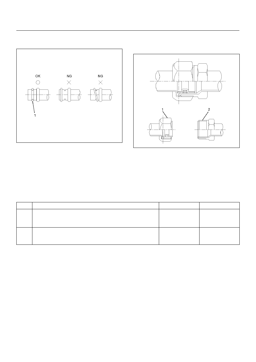
O-rings (2) must be fitted in the groove (1) of refrigerant
line.

850RW003

Insert the nut into the union.
First, tighten the nut by hand as much as possible, then
tighten the nut to the specified torque.

Leak Check

Inspection of refrigerant leak

Refrigerant leak may cause an adverse effect not only
on the performance and durability of each component of
the air-conditioner, but also on the global atmosphere.
Therefore, it is most important to repair refrigerant leak
when there is any leak found.

Inspection flow of refrigerant leak

Inspection Steps

Check the components of air-conditioner to see if there
occurs any refrigerant leak along the flow of refrigerant.

• To avoid an error in the detection of refrigerant leak,

make sure of there being no refrigerant vapor or
cigarette smoke around the vehicle before conducting
the inspection. Also, select a location where the
refrigerant vapor will not get blown off with wind.

• Inspection should be conducted chiefly on the pipe

connections and sections where a marked oil
contamination is found. When refrigerant is leaking,
oil inside is also leaking at the same time.

• It is possible to visually check the leak from inside the

cooling unit. Follow the method below when
checking. Remove the drain hose or resistor of the

cooling unit, and insert a leak detector to see if there
occurs any leak.

High Pressure Side

1. Discharger section of compressor.

2. Inlet/outlet section of condenser.

3. Inlet/outlet section of receiver driver.

4. Inlet section of cooling unit.

Low Pressure Side

1. Outlet section of cooling unit.

2. Intake section of compressor.

Step

Action

Yes

No

1. Evacuate the refrigerant system.

2. Charge the refrigerant.

Is there any refrigerant leak?

Repair refrigerant 

system.

Go to Step 2.

1. Operate the compressor for more than 5 minutes to raise the

pressure on the high pressure side.

Is there any refrigerant leak at high pressure components?

Repair refrigerant 

system.

Compressor 

operation to be 

confirmed.

HEATING, VENTILATION AND AIR CONDITIONING (HVAC)

1A–49

Major Checking Points of Refrigerant Leak

Compressor

• Pipe connection

• Sealing section of shaft

• Mating section or cylinder

Condenser

• Pipe connection

• Welds of condenser body

Receiver driver

• Pipe connection

• Attaching section of pressure switch

• Section around the sight glass

Evaporator unit (cooling unit)

• Pipe connections

• Connections of expansion valve

• Brazed sections of evaporator

• The evaporator and expansion valve are contained in

the case. Remove the drain hose or the resistor of the
cooling unit and insert a leak detector when checking
for any leak.

Flexible hose

• Pipe connection

• Caulking section of the hose

• Hose (cracks, pinholes, flaws)

Pipe

• Pipe connection

• Pipe (cracks, flaws)

Charge valve

• The charge valve, which is used to connect the gauge

manifold, is normally provided with a resin cap. When
the valve inside gets deteriorated, refrigerant will leak
out.

Leak at Refrigerant Line Connections

1. Check the torque on the refrigerant line fitting and, if

too loose, tighten to the specified torque.

• Use two wrenches to prevent twisting and

damage to the line.

• Do not over tighten.

2. Perform a leak test on the refrigerant line fitting.

3. If the leak is still present, discharge and recover the

refrigerant from the system.

4. Replace the O-rings.

• O-rings cannot be reused. Always replace with

new ones.

• Be sure to apply the specified compressor oil to

the new O-rings.

5. Retighten the refrigerant line fitting to the specified

torque.

• Use two wrenches to prevent twisting and

damage to the line.

6. Evacuate, charge and retest the system.

Leaks In The Hose

If the compressor inlet or outlet hose is leaking, the
entire hose must be replaced. The refrigerant hose must
not be cut or spliced for repair.

1. Locate the leak.

2. Discharge and recover the refrigerant.

3. Remove the hose assembly.

• Cap the open connections at once.

4. Connect the new hose assembly.

• Use two wrenches to prevent twisting or damage

to the hose fitting.

• Tighten the hose fitting to the specified torque.

5. Evacuate, charge and test the system.

Compressor Leaks

If leaks are located around the compressor shaft seal or
shell, replace or repair the compressor.

Recovery, Recycling, Evacuation and
Charging of HFC-134a

Air conditioning systems contain HFC-134a. This is a
chemical mixture which requires special handling
procedures to avoid personal injury.

• Always wear safety goggles and protective gloves.

• Always work in a well-ventilated area. Do not weld or

steam clean on or near any vehicle-installed air
conditioning lines or components.

• If HFC-134a should come in contact with any part of

the body, flush the exposed area with cold water and
immediately seek medical help.

• If it is necessary to transport or carry any container of

HFC-134a in a vehicle, do not carry it in the
passenger compartment.

• If it is necessary to fill a small HFC-134a container

from a large one, never fill the container completely.
Space should always be allowed above the liquid for
expansion.

• HFC-134a and R-12 should never be mixed as their

compositions are not the same.

• HFC-134a PAG oil tends to absorb moisture more

quickly than R-12 mineral oil and, therefore, should
be handled more carefully.

• Keep HFC-134a containers stored below 40

°

C

(100

°

F).

1A–50

HEATING, VENTILATION AND AIR CONDITIONING (HVAC)

WARNING:

• SHOULD HFC-134A CONTACT YOUR EYE(S),

CONSULT A DOCTOR IMMEDIATELY.

• DO NOT RUB THE AFFECTED EYE(S). INSTEAD,

SPLASH QUANTITIES OF FRESH COLD WATER
OVER THE AFFECTED     AREA TO GRADUALLY
RAISE THE TEMPERATURE OF THE
REFRIGERANT ABOVE THE FREEZING POINT.

• OBTAIN PROPER MEDICAL TREATMENT AS

SOON AS POSSIBLE. SHOULD THE HFC-134A
TOUCH THE SKIN, THE INJURY MUST BE
TREATED THE SAME AS SKIN WHICH HAS BEEN
FROSTBITTEN OR FROZEN.

Refrigerant Recovery

The refrigerant must be discharged and recovered by
using the J-39500 (ACR

4

:HFC-134a Refrigerant

Recovery/Recycling/Recharging/System) or equivalent
before removing or mounting air conditioning parts.

1. Connect the high and low charging hoses of the

ACR

4

(or equivalent) as shown below.

901RX057

EndOFCallout

2. Recover the refrigerant by following the

Manufacturer's Instructions.

3. When a part is removed, put a cap or a plug on the

connecting portion so that dust, dirt or moisture
cannot get into it.

Refrigerant Recycling

Recycle the refrigerant recovered by J-39500
(ACR

4

:HFC-134a Refrigerant Recovery / Recycling /

Recharging / System) or equivalent.
For the details of the actual operation, follow the steps in
the ACR

4

(or equivalent) Manufacturer's Instructions.

Evacuation of The Refrigerant System

901RX058

EndOFCallout

Explained below is a method using a vacuum pump.
Refer to the ACR

4

(or equivalent) manufacturer's

instructions when evacuating the system with a ACR

4

(or

equivalent).
Air and moisture in the refrigerant will cause problems in
the air conditioning system. Therefore, before charging
the refrigerant, be sure to evacuate air and moisture
thoroughly from the system.

1. Connect the gauge manifold.

• High-pressure valve (HI) — Discharge-side.

• Low-pressure valve (LOW) — Suction-side.

2. Discharge and recover the refrigerant.

3. Connect the center hose of the gauge manifold set

to the vacuum pump inlet.

4. Operate the vacuum pump, open shutoff valve and

then open both hand valves.

5. When the low-pressure gauge indicates

approximately 750 mmHg (30inHg), continue the
evacuation for 5 minutes or more.

6. Close both hand valves and stop the vacuum pump.

Legend

(1) High Side
(2) Low Side

Legend

(1) High Side
(2) Low Side

HEATING, VENTILATION AND AIR CONDITIONING (HVAC)

1A–51

7. Check to ensure that the pressure does not change

after 10 minutes or more.

• If the pressure changes, check the system for

leaks.

• If leaks occur, retighten the refrigerant line

connections and repeat the evacuation steps.

8. If no leaks are found, again operate the vacuum

pump for 20 minutes or more.  After confirming that
the gauge manifold pressure is at 750 mmHg
(30 inHg),     close both hand valves.

9. Close positive shutoff valve. Stop the vacuum pump

and disconnect the center hose from the vacuum
pump.

Charging The Refrigerant System

There are various methods of charging refrigerant into
the air conditioning system.
These include using J-39500 (ACR

4

:HFC-134a

Refrigerant Recovery/Recycling/Recharging/System) or
equivalent and direct charging with a weight scale
charging station.

Charging Procedure

• ACR

4

(or equivalent) Method

For the charging of refrigerant recovered by ACR

4

(or

equivalent), follow the manufacturer's instruction.

901RX057

EndOFCallout

• Direct charging with a weight scale charging

station method

1. Make sure the evacuation process is correctly

completed.

2. Connect the center hose of the manifold gauge to

the weight scale.

3. Connect the low pressure charging hose of the

manifold gauge to the low pressure side service
valve of the vehicle.

4. Connect the high pressure charging hose of the

manifold gauge to the high pressure side service
valve of the vehicle.

901RX059

EndOFCallout

5. Place the refrigerant container up right on a weight

scale.
Note the total weight before charging the refrigerant.

a

Open the refrigerant container valve.

b

Open the low side vale on the manifold gauge
set. Refer to the manufacturer's instructions for
a weight scale charging station.

Legend

(1) High Side
(2) Low Side

Legend

(1) Weight Scale
(2) Refrigerant Container
(3) High Side
(4) Low Side


Content   ..  17  18  19  20   ..