Opel Frontera UE. Manual - part 10


  Index      Opel     Opel Frontera UE - service repair manual 1999-2001 year


Search            


Content   ..  8  9  10  11   ..


Opel Frontera UE. Manual - part 10


1A–12

HEATING, VENTILATION AND AIR CONDITIONING (HVAC)

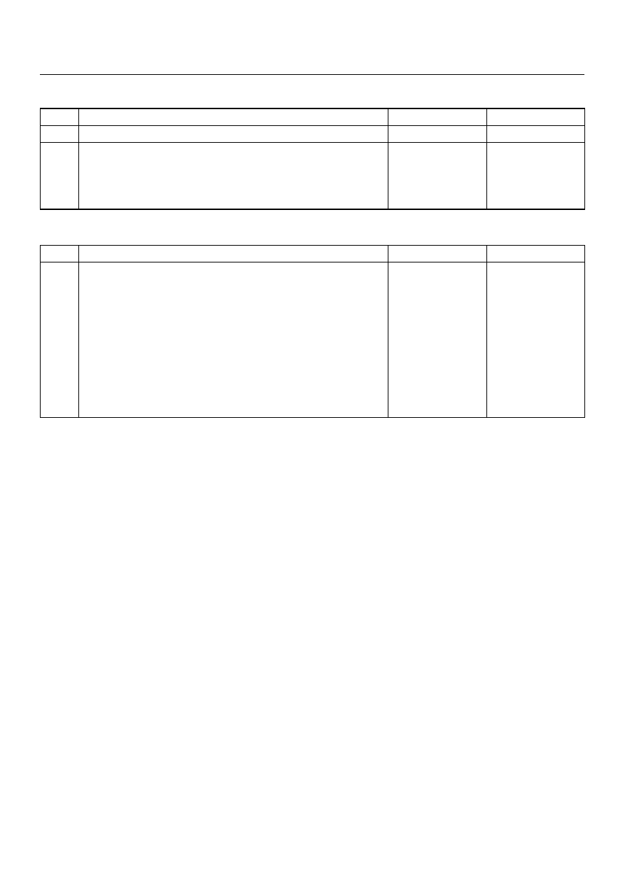
Chart “E" Blower Motor Does Not Run At High Position

Chart “F" Blower Motor Does Not Stop In The “OFF" Position   

Step

Action

Yes

No

Is resistor OK?

Go to Step 2

Replace

Is fan control lever (Fan Switch) OK?

Open circuit 

between Chassis 

side connector 

terminal No. B3-3 

and No. I23-5.

Replace control 

lever assembly.

Step

Action

Yes

No

Is the fan control lever (Fan Switch) OK?

Short circuit 

between chassis 

side connector 

terminal No.B5-1 

and 

No.B3-2,No.B3-3 

and No.I23-5, 

No.B3-6 and 

No.I23-4, No.B3-4 

and No.I23-3 or 

No.B3-1 and 

No.I23-2

Replace control 

lever assembly.

HEATING, VENTILATION AND AIR CONDITIONING (HVAC)

1A–13

Individual Inspection

Blower Motor

1. Disconnect the blower motor (B-5) connector from

the blower motor.

2. Connect the battery positive terminal to the No. 2

terminal of the blower motor and the negative to the
No. 1.

3. Be sure to check to see if the blower motor operates

correctly.

873RW008

Resistor

1. Disconnect the resistor (B-3) connector.

2. Check for continuity and resistance between the

terminals of the resistor.

840RX013

EndOFCallout

Legend

(1) Resister Assembly
(2) Connector Terminal (Resister Side)
(3) Position Switch

1A–14

HEATING, VENTILATION AND AIR CONDITIONING (HVAC)

Fan Control Lever (Fan Switch)

1. Check for continuity between the terminals of the

fan switch.

D08RX157

EndOFCallout

Heater Relay

1. Disconnect the heater relay (X-6).

• When removing the connector for relay, unfasten

the tank lock of the connector by using a
screwdriver, then pull the relay (1) out.

825RX046

2. Check for continuity between the heater relay (X-6)

terminals.

901RX071

Legend

(1) Control Lever Connector Terminal (Control 

Lever Side)

(2) Position Switch

HEATING, VENTILATION AND AIR CONDITIONING (HVAC)

1A–15

Heater Unit

Heater Unit and Associated Parts

840RX006

EndOFCallout

Removal

1. Disconnect the battery ground cable.

2. Drain the engine coolant.

3. Discharge and recover refrigerant (with air

conditioning).

• Refer to Refrigerant Recovery in this section.

4. Remove the Instrument panel assembly.

• Refer to Instrument Panel Assembly in Body and

Accessories section.

5. Remove instrument panel bracket.

• Refer to Cross Beam Assembly in Body and

Accessories section.

6. Cross Beam Assembly.

• Refer to Cross Beam Assembly in Body and

Accessories section.

7. Disconnect resistor connector.

8. Remove duct.

9. Remove evaporator assembly (A/C only).

• Refer to Evaporator Assembly in this section.

10. Remove driver lap vent duct.

11. Remove ventilation lower duct.

12. Remove rear heater duct.

• Remove foot rest, carpet and 3 clips.

13. Remove heater unit assembly.

• Disconnect heater hoses at heater unit.

Legend

(1) Instrument Panel Assembly
(2) Resistor Connector
(3) Heater Hose
(4) Heater Unit Assembly
(5) Duct (W/O A/C)

(6) Evaporator Assembly (With A/C)
(7) Lap Vent Duct
(8) Rear Heater Duct
(9) Ventilation Lower Duct

(10) Instrument Panel Bracket
(11) Cross Beam Assembly


Content   ..  8  9  10  11   ..