Nissan Frontier (2023 year). Manual in english - page 29


  Index      Manuals     Nissan Frontier (2023 year). Manual in english


Search            copyright infringement  


Content      ..     27      28      29      30     ..


Nissan Frontier (2023 year). Manual in english - page 29


CAUTION

After wiper blade replacement, re-
turn the wiper arm to its original po-
sition; otherwise it may be damaged
when the hood is opened.

Make sure the wiper blades contact
the glass; otherwise the arms may be
damaged from wind pressure.

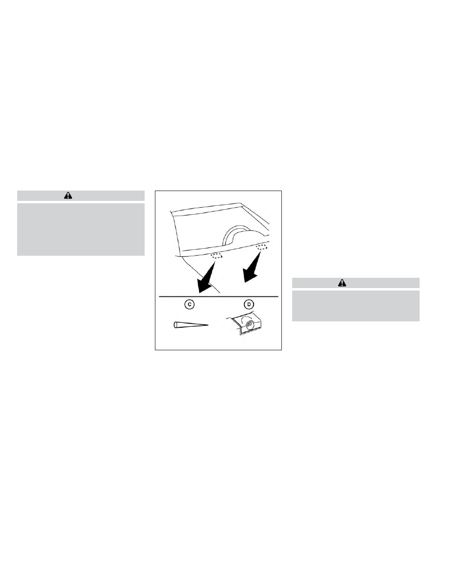
Be careful not to let anything get into the
washer nozzle

O

D

. This may cause clogging

or improper windshield–washer operation.
If something gets into the nozzle, remove it
with a needle or small pin

O

C

.

If the brakes do not operate properly, have
the brakes checked. It is recommended
that you visit a NISSAN dealer for this
service.

Self-adjusting brakes

Your vehicle is equipped with self-adjusting
brakes.

The front and rear disc-type brakes self-
adjust every time the brake pedal is
applied.

WARNING

Have your brake system checked if the
brake pedal height does not return to
normal. It is recommended that you
visit a NISSAN dealer for this service.

Brake pad wear indicators

The disc brake pads on your vehicle have
audible wear indicators. When a brake pad
requires

replacement,

a

high

pitched

scraping or screeching sound will be heard
when the vehicle is in motion. The noise will
be heard whether or not the brake pedal is
depressed. Have the brakes checked as
soon as possible if the wear indicator
sound is heard.

LDI2710

BRAKES

8-22

Do-it-yourself

-------------------------------------------------------------------------------------------------------------------------------------------------------------

Under some driving or climate conditions,
occasional brake squeak, squeal or other
noise may be heard. Occasional brake
noise during light to moderate stops is nor-
mal and does not affect the function or
performance of the brake system.

Proper brake inspection intervals should
be followed.

For additional information re-

garding brake inspections, see the appro-
priate maintenance schedule information
in the "Maintenance and schedules" sec-
tion of this manual.

Two types of fuses are used. Type

O

A

is

used in the fuse boxes in the engine com-
partment. Type

O

B

is used in the passenger

compartment and engine compartment
fuse boxes. Type

O

A

fuses are provided as

spare fuses. There are no spare fuses in the
engine compartment.

If a type

O

A

fuse is used to replace a type

O

B

fuse, the type

O

A

fuse will not be level with

the fuse pocket as shown in the illustration.
This will not affect the performance of the
fuse. Make sure the fuse is installed in the
fuse box securely.

Type

O

B

fuses cannot be installed in the

underhood fuse boxes. Only use type

O

A

fuses in the underhood fuse boxes.

NOTE:

Your vehicle may not be equipped with
all fuses listed on the fuse label.

LDI0455

LDI0457

FUSES

Do-it-yourself

8-23

-------------------------------------------------------------------------------------------------------------------------------------------------------------

ENGINE COMPARTMENT

WARNING

Never use a fuse of a higher or lower
amperage rating than that specified on
the fuse box cover. This could damage
the electrical system or electronic con-
trol units or cause a fire.

If any electrical equipment does not come
on, check for an open fuse.

1. Be sure the ignition switch and the head-

light switch are OFF.

2. Open the engine hood.

3. Remove the fuse box cover by pushing

the tab and lifting the cover up.

4. Remove the fuse with the fuse puller.

The fuse puller is located in the center
of the fuse block in the passenger
compartment.

LDI2838

LDI2826

8-24

Do-it-yourself

-------------------------------------------------------------------------------------------------------------------------------------------------------------

5. If the fuse is open

O

A

, replace it with a

new fuse

O

B

.

6. If a new fuse also opens, have the elec-

trical system checked and repaired. It is
recommended that you visit a NISSAN
dealer for this service.

Fusible links

If the electrical equipment does not oper-
ate and fuses are in good condition, check
the fusible links. If any of these fusible links
are melted, replace with only Genuine
NISSAN parts.

PASSENGER COMPARTMENT

WARNING

Never use a fuse of a higher or lower
amperage rating than that specified on
the fuse box cover. This could damage
the electrical system or electronic con-
trol units or cause a fire.

If any electrical equipment does not oper-
ate, check for an open fuse.

1. Be sure the ignition switch and the head-

light switch are OFF.

2. Open glove box and pull the fuse box

cover to remove.

3. Remove the fuse with the fuse puller.

LDI0456

LDI3640

Do-it-yourself

8-25

-------------------------------------------------------------------------------------------------------------------------------------------------------------

4. If the fuse is open

O

A

, replace it with an

equivalent good fuse

O

B

.

5. Reverse step 2 to reinstall fuse box cover.

6. If a new fuse also opens, have the elec-

trical system checked and repaired. It is
recommended that you visit a NISSAN
dealer for this service.

NOTE:

Your vehicle may not be equipped with
all fuses listed on the fuse label.

CAUTION

Be careful not to allow children to swal-
low the battery or removed parts.

NISSAN INTELLIGENT KEY®

LDI0456

LDI2001

BATTERY REPLACEMENT

8-26

Do-it-yourself

-------------------------------------------------------------------------------------------------------------------------------------------------------------

Replace the battery in the Intelligent Key as
follows:

1. Remove the mechanical key from the

Intelligent Key.

2. Insert a small flathead screwdriver

O

A

into the slit

O

B

of the corner and twist it

to separate the upper part from the
lower part. Place a cloth over the screw-
driver to protect the casing.

3. Replace the battery with a new one.

Recommended

battery:

CR2032

or

equivalent.

• Do not touch the internal circuit and

electric terminals as doing so could
cause a malfunction.

• Hold the battery by the edges. Holding

the battery across the contact points
will seriously deplete the storage
capacity.

• Make sure that the + side faces the

bottom of the lower part.

4. Close the lid securely as illustrated with

O

C

and

O

D

.

5. Operate the buttons to check the

operation.

If you need assistance with replacement, it
is recommended that you visit a NISSAN
dealer for this service.

FCC Notice:
For USA:
This device complies with Part 15 of the
FCC Rules. Operation is subject to the fol-
lowing two conditions: (1) This device
may not cause harmful interference, and
(2) this device must accept any interfer-
ence received, including interference
that may cause undesired operation.

LDI2637

Do-it-yourself

8-27

-------------------------------------------------------------------------------------------------------------------------------------------------------------

Note:

Changes or modifications not expressly
approved by the party responsible for
compliance could void the user’s author-
ity to operate the equipment.

For Canada:
This

device

contains

licence-exempt

transmitter(s)/receiver(s) that comply
with Innovation, Science and Economic
Development Canada’s licence-exempt
RSS(s). Operation is subject to the fol-
lowing two conditions: (1) This device
may not cause interference. (2) This de-
vice must accept any interference, in-
cluding interference that may cause un-
desired operation of the device.

HEADLIGHTS

For additional information on headlight
bulb replacement, refer to the instructions
outlined in this section.

Replacing the halogen headlight
bulb (if so equipped)

The headlight is a semi-sealed beam type
which uses a replaceable headlight (halo-
gen) bulb. Because the headlight assembly
must be removed from the vehicle for bulb
replacement, it is recommended that you
visit a NISSAN dealer for this service.

CAUTION

High pressure halogen gas is sealed
inside the halogen bulb. The bulb
may break if the glass envelope is
scratched or the bulb is dropped.

When handling the bulb, do not touch
the glass envelope.

DO NOT TOUCH THE BULB WITH BARE
HANDS.

Use the same number and wattage
as shown in the chart.

Do not leave the bulb out of the head-
light reflector for a long period of time
as dust, moisture and smoke may en-
ter the headlight body and affect the
performance of the headlight.

Aiming is not necessary after replac-
ing the bulb. When aiming adjust-
ment is necessary, it is recom-
mended that you visit a NISSAN
dealer for this service.

Fog may temporarily form inside the lens
of the exterior lights in the rain or in a car
wash. A temperature difference between
the inside and the outside of the lens
causes the fog. This is not a malfunction. If
large drops of water collect inside the lens,
it is recommended that you visit a NISSAN
dealer for servicing.

Replacing the LED headlight bulb
(if so equipped)

If LED headlight bulb replacement is re-
quired, it is recommended that you visit a
NISSAN dealer for this service.

FOG LIGHTS (if so equipped)

For additional information on fog light bulb
replacement, refer to the instructions out-
lined in this section.

LIGHTS

8-28

Do-it-yourself

-------------------------------------------------------------------------------------------------------------------------------------------------------------

Replacing the fog light bulb (if so
equipped)

If fog light bulb replacement is required, it is
recommended that you visit a NISSAN
dealer for this service.

CAUTION

High pressure halogen gas is sealed
inside the halogen bulb. The bulb
may break if the glass envelope is
scratched or the bulb is dropped.

When handling the bulb, do not touch
the glass envelope.

Use the same number and wattage
as originally installed as shown in the
chart.

Do not leave the bulb out of the fog
light for a long period of time as dust,
moisture and smoke may enter the
fog light body and affect the perfor-
mance of the fog light.

Replacing the LED fog light bulb
(if so equipped)

If LED fog light bulb replacement is re-
quired, it is recommended that you visit a
NISSAN dealer for this service.

EXTERIOR AND INTERIOR LIGHTS

Item

Wattage (W)

Bulb No.*

Headlight assembly (Type A) (if so equipped)*

Low/High

55/65

HB5

Turn/Park

28/8

7444NA

Side marker

Headlight assembly (Type B) (if so equipped)*

Low

High

Turn

Daytime Running Light (DRL)/Park

Side marker

Fog light (if so equipped)*

Fog light assembly (if so equipped)*

Fog

35

H8

Daytime Running Light (DRL)

21

W21W

Map light (Type A) (if so equipped)

8

Map light (Type B) (if so equipped)*

Vanity mirror light (if so equipped)*

1.4

Room light (Type A) (if so equipped)

8

Room light (Type B) (if so equipped)*

Glove box light (if so equipped)*

1

High-mounted stop light/cargo light*

12.8

912

Bed light (if so equipped)*

Rear combination light*

Tail

Stop/turn

Backup

License plate light*

* It is recommended that you visit a NISSAN dealer for replacement.

Always check with the Parts Department at a NISSAN dealer for the latest parts
information.

Do-it-yourself

8-29

-------------------------------------------------------------------------------------------------------------------------------------------------------------

1.

Room light

2.

Map light

3.

Headlight assembly

4.

Fog light/Fog light assembly (if so
equipped)

5.

Bed light (if so equipped)

6.

High-mount stop light/cargo light

7.

Rear combination light

8.

License plate light

LDI3631

8-30

Do-it-yourself

-------------------------------------------------------------------------------------------------------------------------------------------------------------

Replacement procedures

All other lights are either type A, B, C or D.
When replacing a bulb, first remove the lens
and/or cover using a cloth and suitable tool.

: Indicates bulb removal

: Indicates bulb installation

Use a cloth

O

1

to protect the housing.

Use a cloth

O

1

to protect the housing.

WDI0306

LDI0478

Map light (Type A) (if so equipped)

WDI0206

Room light (Type A) (if so equipped)

Do-it-yourself

8-31

-------------------------------------------------------------------------------------------------------------------------------------------------------------

If you have a flat tire, see “Flat tire”
(P. 6-3).

TIRE PRESSURE

Tire Pressure Monitoring System
(TPMS)

WARNING

Radio waves could adversely af-
fect electric medical equipment.
Those who use a pacemaker
should contact the electric medi-
cal equipment manufacturer for
the possible influences before
use.

This vehicle is equipped with TPMS. It
monitors tire pressure of all tires ex-
cept the spare. When the low tire
pressure warning light is lit and the
“Tire Pressure Low - Add Air” warning
message is displayed in the vehicle
information display, one or more
of your tires is significantly under-
inflated.

TPMS will activate only when the ve-
hicle is driven at speeds above 16
mph (25 km/h). Also, this system
may not detect a sudden drop in tire
pressure (for example, a flat tire while
driving).

For additional information, see “Low
tire pressure warning light” (P. 2-17),
“Tire Pressure Monitoring System
(TPMS)” (P. 5-5) and “Flat tire” in the
(P. 6-3).

Tire inflation pressure

Check the tire pressures (including
the spare) often and always prior to
long distance trips. The recom-
mended tire pressure specifications
are shown on the F.M.V.S.S./C.M.V.S.S.
certification label or the Tire and
Loading Information label under the
“Cold Tire Pressure” heading. The Tire
and Loading Information label is af-
fixed to the driver side center pillar.

Tire pressures should be checked
regularly because:

• Most tires naturally lose air over

time.

• Tires can lose air suddenly when

driven over potholes or other ob-
jects or if the vehicle strikes a curb
while parking.

The

tire

pressures

should

be

checked when the tires are cold. The
tires are considered COLD after the
vehicle has been parked for 3 or
more hours, or driven less than 1 mile
(1.6 km) at moderate speeds.

Incorrect tire pressure, including
under inflation, may adversely af-
fect tire life and vehicle handling.

WHEELS AND TIRES

8-32

Do-it-yourself

-------------------------------------------------------------------------------------------------------------------------------------------------------------

WARNING

Improperly inflated tires can
fail suddenly and cause an
accident.

The Gross Vehicle Weight Rat-
ing (GVWR) is located on the
F.M.V.S.S./C.M.V.S.S.

certifica-

tion label. The vehicle weight
capacity is indicated on the Tire
and Loading Information label.
Do not load your vehicle be-
yond this capacity. Overload-
ing your vehicle may result in
reduced tire life, unsafe operat-
ing conditions due to prema-
ture tire failure, or unfavorable
handling characteristics and
could also lead to a serious ac-
cident. Loading beyond the
specified capacity may also re-
sult in failure of other vehicle
components.

Before taking a long trip, or
whenever

you

heavily

load

your vehicle, use a tire pressure
gauge to ensure that the tire
pressures are at the specified
level.

For additional information re-
garding tires, refer to “Impor-
tant Tire Safety Information”
(US) or “Tire Safety Informa-
tion” (Canada) in the Warranty
Information Booklet.

Do-it-yourself

8-33

-------------------------------------------------------------------------------------------------------------------------------------------------------------

Tire and Loading Information
label

1

Seating capacity: The maximum
number of occupants that can
be seated in the vehicle.

2

Vehicle load limit: See “Vehicle
loading information” (P. 10-16).

3

Original tire size: The size of the
tires originally installed on the ve-
hicle at the factory.

4

Cold tire pressure: Inflate the tires
to this pressure when the tires are
cold. Tires are considered COLD
after the vehicle has been parked
for 3 or more hours, or driven less
than 1 mile (1.6 km) at moderate
speeds. The recommended cold
tire inflation is set by the manu-
facturer to provide the best bal-
ance of tire wear, vehicle handling,
driveability, tire noise, etc., up to
the vehicle's GVWR.

5

Tire

size:

See

“Tire

labeling”

(P. 8-36).

6

Spare tire size.

LDI2007

8-34

Do-it-yourself

-------------------------------------------------------------------------------------------------------------------------------------------------------------

Checking tire pressure

1. Remove the valve stem cap from

the tire.

2. Press the pressure gauge squarely

onto the valve stem. Do not press
too hard or force the valve stem
sideways, or air will escape. If the
hissing sound of air escaping from
the tire is heard while checking the
pressure, reposition the gauge to
eliminate this leakage.

3. Remove the gauge.

4. Read the tire pressure on the

gauge stem and compare to the
specification

shown

on

the

F.M.V.S.S./C.M.V.S.S. label or the
Tire

and

Loading

Information

label.

5. Add air to the tire as needed. If too

much air is added, press the core
of the valve stem briefly with the
tip of the gauge stem to release
pressure. Recheck the pressure
and add or release air as needed.

6. Install the valve stem cap.

7. Check the pressure of all other

tires, including the spare.

Size

Cold Tire Inflation

Pressure

kPa

psi

Front and
Rear Original
Tire:
P265/70R16
265/65R17
265/70R17

240

35

Front and
Rear Original
Tire Size:

Spare Tire Size:

P265/70R16
265/65R17
265/70R17

Full Size
P265/70R16
Full Size

LDI0393

Do-it-yourself

8-35

-------------------------------------------------------------------------------------------------------------------------------------------------------------

TIRE LABELING

Federal law requires tire manufac-
turers to place standardized infor-
mation on the sidewall of all tires.
This information identifies and de-
scribes the fundamental character-
istics of the tire and also provides the
Tire Identification Number (TIN) for
safety standard certification. The TIN
can be used to identify the tire in
case of a recall.

O

1

Tire size (example: P215/65R15

95H)

1. P: The “P” indicates the tire is de-

signed for passenger vehicles (not
all tires have this information).

2. Three-digit number (215): This

number gives the width in milli-
meters of the tire from sidewall
edge to sidewall edge.

3. Two-digit number (65): This num-

ber, known as the aspect ratio,
gives the tire's ratio of height to
width.

4. R: The “R” stands for radial.

5. Two-digit number (15): This num-

ber is the wheel or rim diameter in
inches.

WDI0394

Example

WDI0395

Example

8-36

Do-it-yourself

-------------------------------------------------------------------------------------------------------------------------------------------------------------

6. Two- or three-digit number (95):

This number is the tire's load in-
dex. It is a measurement of how
much

weight

each

tire

can

support.

7. H: Tire speed rating. You should

not drive the vehicle faster than
the tire speed rating.

O

2

TIN (Tire Identification Number)

for a new tire (example: DOT XX XX
XXX XXXX)

1. DOT: Abbreviation for the “Depart-

ment

Of

Transportation”.

The

symbol can be placed above, be-
low or to the left or right of the Tire
Identification Number.

2. Two-digit code: Manufacturer's

identification mark.

3. Two-digit code: Tire size.

4. Three-digit code: Tire type code

(Optional).

5. Four

numbers

represent

the

week and year the tire was built.
For example, the numbers 3103
means the 31st week of 2003. If
these numbers are missing then
look on the other sidewall of the
tire.

LDI2786

Example (Type A) (if so equipped)

Do-it-yourself

8-37

-------------------------------------------------------------------------------------------------------------------------------------------------------------


Content      ..     27      28      29      30     ..