Nissan Titan (2022 year). Manual in english - page 7
Vehicle damage (or lack of it) is not always
an indication of proper knee air bag
operation.
When the knee air bag inflates, a fairly loud
noise may be heard, followed by release of
smoke. This smoke is not harmful and
does not indicate a fire. Care should be
taken not to inhale it, as it may cause irrita-
tion and choking. Those with a history of a
breathing condition should get fresh air
promptly.
The knee air bag helps to cushion the im-
pact force on the knees of the driver and
passenger. It can help reduce serious inju-
ries. However, an inflating knee air bag may
cause abrasions or other injuries. The knee
air bag provides restraint to the lower body.
The knee air bag inflates quickly in order to
help protect the occupants. Because of
this, the force of the knee air bag inflating
can increase the risk of injury if the occu-
pant is too close to, or is against, this air bag
module during inflation. The knee air bag
will deflate quickly after the collision is over
OR the knee air bag will remain inflated for
a short time.
The knee air bag operates only when the
power switch is placed in the ON
position.
After placing the power switch in the ON
position,
the
supplemental
air
bag
warning light illuminates. The supple-
mental air bag warning light will turn off
after about 7 seconds if the system is
operational.
WARNING
•
Do not place any objects between the
knee bolster and the driver’s or pas-
senger’s seat. Such objects may be-
come
dangerous
projectiles
and
cause injury if a knee air bag inflates.
•
Right after inflation, the knee air bag
system components will be hot. Do
not touch them; you may severely
burn yourself.
•
No unauthorized changes should be
made to any components or wiring
of the knee air bag system. This is to
prevent damage to or accidental in-
flation of the knee air bag system.
•
Do not make unauthorized changes
to your vehicle's electrical system or
suspension system. This could affect
proper operation of the knee air bag
system.
•
Tampering with the knee air bag sys-
tem may result in serious personal
injury. For example, do not change
the driver or passenger knee bolster
or install additional trim material
around the knee air bag.
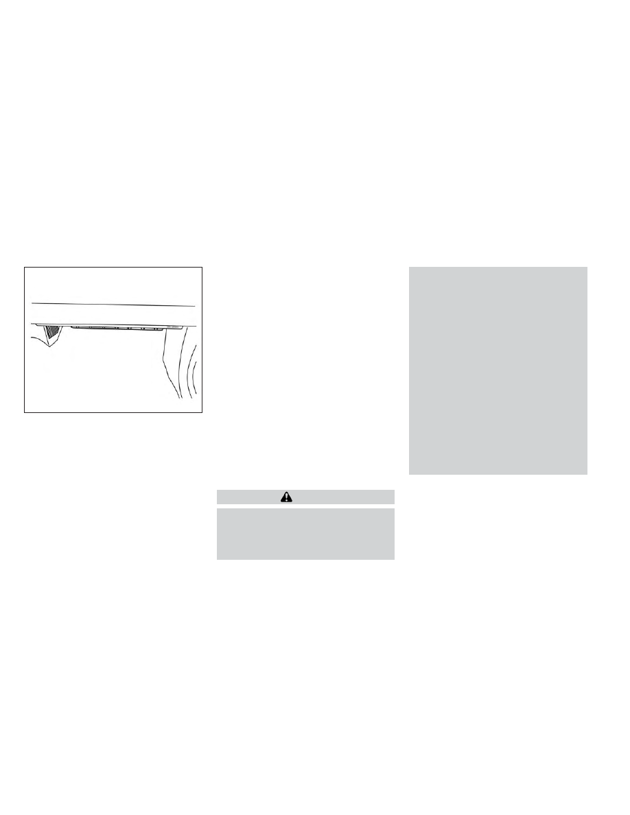
LRS3244
Passenger’s side
Safety-Seats, seat belts and supplemental restraint system
1-81